ClearSCADA supports 4 of the languages included in the International Electro-technical Commission (IEC) standard for programming industrial control systems (IEC 1131-3). Each language behaves differently and each has its own pros and cons. The following descriptions of each language may be used as a simple guide in helping to determine which language to use for particular situations in ClearSCADA.
The information described below does not provide any hard and fast rules for the selection of a language, but merely a guide to help understand the relative benefits of the languages available.
Ladder Diagrams
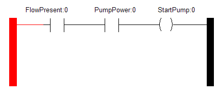
Ladder logic is widely used to program PLCs, where sequential control of a process or manufacturing operation is required. As programmable logic controllers became more sophisticated it has also been used in very complex automation systems. In appearance it is very similar to existing (AB/Omron/Mitsubishi etc) PLC ladder logic.

Limitations
Ladder logic is best suited to control problems where only binary variables are required and where interlocking and sequencing of binary is the primary control problem. In parallel programming languages, the sequential order of operations may be undefined or obscure; logic race conditions are possible, this may produce unexpected results. Complex rungs are often broken into several simpler steps to avoid this problem. Some manufacturers avoid this problem by explicitly and completely defining the execution order of a rung.
Analog quantities and arithmetical operations are clumsy to express in ladder logic and each manufacturer has different ways of extending the notation for these problems. There is usually limited support for arrays and loops, often resulting in duplication of code to express cases which in other languages would call for use of indexed variables.
As microprocessors have become more powerful, notations such as Sequential Function Charts and Function Block Diagrams can replace ladder logic for some limited applications.
Function Block Diagrams (FBDs)
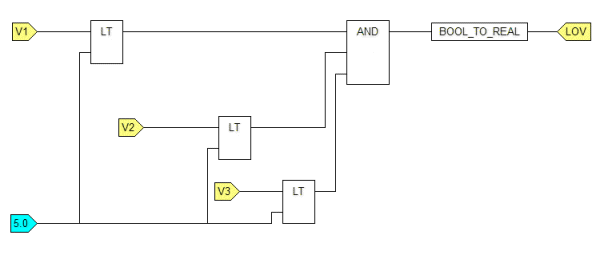
The Function Block Diagram (FBD) is a graphical language that can describe the function between input variables and output variables. A function is described as a set of elementary blocks. Input and output variables are connected to blocks by connection lines.
Inputs and outputs of the blocks are wired together with connection lines, or links. Single lines may be used to connect two logical points of the diagram:
- An input variable and an input of a block
- An output of a block and an input of another block
- An output of a block and an output variable
The connection is oriented, meaning that the line carries associated data from the left end to the right end. The left and right ends of the connection line must be of the same type.
Multiple right connection, also called divergence can be used to broadcast information from its left end to each of its right ends. All ends of the connection must be of the same type.

Limitations
FBDs are not ideal for large programs using special I/O and functions. The large amount of screen space required by this style of programming can quickly make a program unwieldy if it reaches any substantial size.
Writing or drawing a program in Function Block requires more preparation upfront to understand the program and how it will flow before any code is written, since it can be more difficult to make corrections later
FBDs in ClearSCADA cannot be used to issue methods.
Drawing of FBDs can be slower than writing Structured Text when only simple functions are performed.
Sequential Function Charts (SFCs)
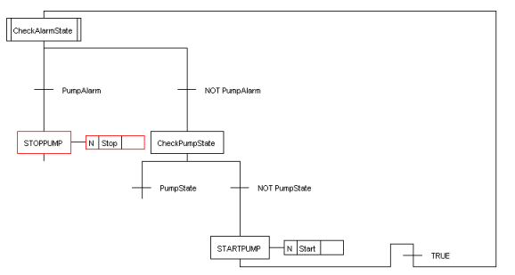
Sequential Function Chart (SFC) programming resembles computer programming flowcharts. An initial step “action box” (the starting point of a flowchart) is followed by a series of transitions and additional action steps.
This form of programming is the easiest to implement for applications that have a repeatable multi-step process or series of repeatable processes,

Limitations
A large amount of time must be spent up front preparing and planning before any programming is attempted or else the functions charts could become unwieldy and difficult to follow.
This language is linear, reducing its flexibility and future expansion.
Structured Text programs (ST)
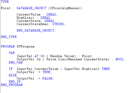
This is a high level language that is block structured and syntactically resembles Pascal, on which it is based. It is highly flexible in both operation and configuration. Its use in ClearSCADA has the following benefits:
- Methods can be issued.
- Internal data via SQL can be accessed.
- Raw and processed historic data can be accessed.
- It has extensions allowing parameters to be passed in.
- Supports indirect variables (using parameters passed in).
- Internal tables can be written to via SQL.
- Local files and COM ports can be written to.
- Arrays are supported using the VECTOR keyword.

Limitations
Structured Text requires prior coding experience to use it effectively and without problem, it has a steep learning curve otherwise.
It can be difficult to understand execution cycles.
Timing functions (e.g. TON and TOF) not as simple as in other languages.
In ClearSCADA these languages are referred to as Logic programs, and you can use them to:
- Define complex relationships between the values for the properties of items in the database
- Perform calculations
- Execute methods on items in the database (one shots, overrides, controls etc.)
For example, in the water industry, a Function Block Diagram can be used to turn pumps on when the water level drops to a specified limit.
The Logic programs are interchangeable—you can use one type of Logic program with a different type of Logic program. For example, you can use ST programs with Function Block Diagrams or Ladder Diagrams. The only exception is Sequential Function Charts which can only be used with ST programs.