Many simple drivers that support analog points also support scaling of the raw analog values into ‘engineering’ values that can be used within the ClearSCADA database. Scaling allows the raw signal values from plant to be scaled into more appropriate values for use within ClearSCADA and vice versa.
You typically configure scaling on the <Driver Type> tab of the appropriate Analog Point Form. This section explains the scaling properties that exist for analog points on many simple drivers. The driver-specific documentation mentions whether scaling is supported, or whether scaling properties differ, for the analog points on a particular driver.
Where supported by a driver, you use the fields within the Scaling section of the <Driver Type> tab to specify whether scaling of raw input values is required:

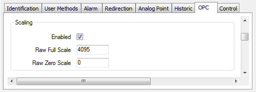
- Enabled—Select this check box if the raw input values are to be scaled for use in ClearSCADA, or vice versa for any output values. Use the fields in the rest of the Scaling section to define the scaling that is required—the range of raw signal values is scaled to the range of values specified in the Alarm Limits section of the Analog Point tab, when a value is used in ClearSCADA, and vice versa whenever ClearSCADA sets an analog value on a device.
Clear the Enabled check box if scaling is not required. The raw input signals are used directly in ClearSCADA, without any scaling adjustment. (In other words, the Raw Full Scale and the Raw Zero Scale of the input value are identical to the Full Scale and Zero Scale settings specified in the Alarm Limits section of the Analog Point tab.) The other fields in the Scaling section are ‘grayed out’ and unavailable for use.
- Raw Full Scale—Applies when Scaling is enabled. Enter the highest acceptable raw data value for the point (the full scale of the instrument or control device that this point represents).
For analog points on many simple drivers, you need to enter the appropriate value within the range 1 to 65535 (the driver-specific documentation mentions if this range differs).
When used in ClearSCADA, the driver scales the Raw Full Scale value to the value that is specified in the Full Scale Limit field on the Analog Point tab.
- Raw Zero Scale—Applies when Scaling is enabled. Enter the lowest acceptable raw data value for the point (the zero scale of the instrument or control device that this point represents).
For analog points on many simple drivers, you need to enter the appropriate value within the range 0 to 65534 (the driver-specific documentation mentions if this range differs).
When used in ClearSCADA, the driver scales the Raw Zero Scale value to the value that is specified in the Zero Scale Limit field on the Analog Point tab.
Example:
An Analog point has a raw scale of 0 to 4095 (12-bit). This is to correspond in ClearSCADA to an engineering scale of 0 to 10.
On the Form for the point, Scaling is enabled and configured with the raw value range:

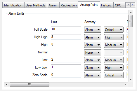
In the Alarm Limits section of the Form, the engineering scale values are specified, along with any limits that indicate notable changes in operating condition:

As such, the Full Scale engineering value of 10 corresponds to the Raw Full Scale value of 4095 and the Zero Scale engineering value of 0 corresponds to the Raw Zero Scale value of 0.
The usual operating range of the plant is defined by the Normal state, which in engineering terms is when the value is between 2 and 8. This corresponds to a raw operating range of 819 to 3276.
Therefore, from normal operating conditions, if the raw value rises to 3276 or above, when that value is reported to the server, ClearSCADA will raise an alarm, as the value has exceeded the High Limit of 8 (which corresponds to the raw value of 3276).
Similarly, if the raw value continues to rise until it reaches 3685.5 or above, ClearSCADA will raise an alarm to indicate that the corresponding engineering value has exceeded the High High Limit of 9 (the engineering equivalent of 3685.5).