You can store alarms from a FloBoss in a ClearSCADA Data Table. The Data Table will have a specific schema entry. Unlike the other FloBoss database objects, Data Tables are generic database objects (see Configuring Data Tables in the ClearSCADA Guide to Core Configuration).
To create a Data Table:
- Right-click on the required group in the Database Bar.
A context-sensitive menu is displayed. - Select the Create New option, followed by the Tables and Grids option.
- Select the Data Table option.
A new Data Table is added to the database. - Specify a suitable name for the Data Table (taking into account the ClearSCADA naming restrictions).
- Right-click on the Data Table entry in the Database Bar and select the Edit Properties option. Specify a suitable Table Name and Title for the table and then save the configuration.
- Do not make any other changes to the table.
The ClearSCADA FloBoss Driver can create the correct columns in the Data Table automatically. To do this, you need to associate the Data Table with the relevant ClearSCADA FloBoss Scanner object. To do this:
- Display the properties window (‘configuration Form’) for the FloBoss Scanner object.
- On the Options tab, locate the Alarms and Events section.
- Use the browse button next to the Alarm Data Table field to display a Reference browse window. Locate and select the Data Table that you have just added to the database.
- Save the configuration changes.
The FloBoss driver will create the correct columns in the Data Table, providing that the Data Table contains 0 records and the Get Alarms option is enabled on the Scanner. (If the referenced data table is not empty, the driver will not create columns, because data loss could possibly occur.)
A correctly configured Alarm Data Table is included in the FloBossDemo.sde file.
A single Data Table can store alarms from multiple flow computers. For the ClearSCADA FloBoss Driver to populate an Alarm Data Table, the table has to contain the columns that are shown in the figure below, with the correct data type at a minimum. Additional columns are allowed, but the driver will only populate those columns that are shown below. The columns that the driver adds to the Alarm Data Table are described below.
The underlying alarms are described in the Opcode 121 section in the ROC Protocol Specifications Manual.
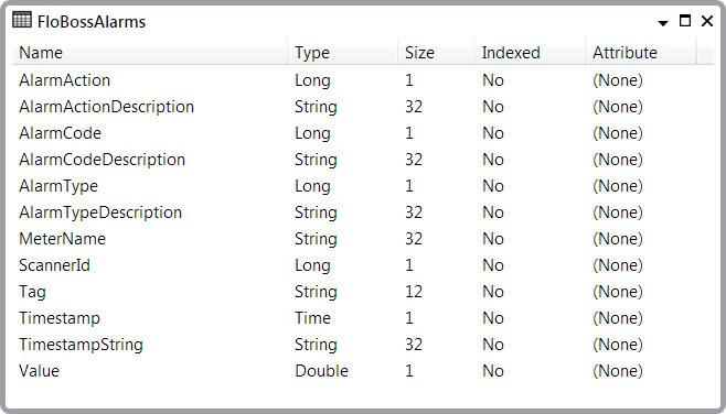
- AlarmAction. A numeric code indicating what the alarm action was. This is the raw value that the driver gets from the FloBoss.
- AlarmActionDescription. The driver’s decoding of the AlarmAction field.
- AlarmCode. A numeric code indicating the reason why the alarm was logged. This is the raw value that the driver gets from the FloBoss.
- AlarmCodeDescription. The driver’s decoding of the AlarmCode field.
- AlarmType. A numeric code indicating the type of alarm. This is the raw value that the driver gets from the FloBoss.
- AlarmTypeDescription. The driver’s decoding of the AlarmType field.
- MeterName. This column is populated with the contents of the Meter Name field on the Scanner tab of the FloBoss Scanner object that retrieved the alarms. This information is provided as a convenient way to filter alarms records from multiple FloBosses.
- ScannerId. This is the ClearSCADA database ID of the FloBoss Scanner object that populated this record in the Alarm Data Table. This information might prove useful in an SQL query as part of a filter or a join.
- Tag. This is the tag from the alarm. This is a 10-character string that the FloBoss uses to describe the alarm.
- Timestamp. This is the time of the alarm with the offset in the FloBoss Time Zone field on the Scanner tab of the FloBoss Scanner object applied. This value is stored in the data table as a UTC time, so it can be used to sort or filter in an SQL query. As this value is stored as a time, ViewX or WebX fixes the value when the Data Table is displayed.
- TimestampString. This is the time of the alarm from the FloBoss with no offsets applied. Because this value is stored as a string, ViewX or WebX do not fix the value when it is displayed. This column is provided for auditability.
- Value. This is the value of the parameter at the time of the alarm.