Define the Point Scaling
Scaling can only be used with outstations configured to use the SOFBUS-PL protocol. Outstations using the LACBUS-RTU protocol perform the scaling internally and report scaled values to ClearSCADA.
Use the fields in the Scaling section of the Analog Input Point Form to specify the type and range of the raw input signals, so that they can be suitably converted into floating-point engineering values for use in the ClearSCADA database.
Conversely, use the section on the Analog Output Point Form to perform a similar conversion on any output signals. ClearSCADA uses the conversion calculation to produce a raw data value that is sent to the point.
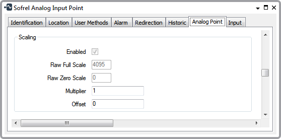
Select this check box if the input value at the controller needs scaling for use by ClearSCADA, and vice versa for output values. The driver receives raw values from the outstation and scales them before storing them in the database. The driver also receives engineering values (for example, when a user issues a control) and scales them to raw values before sending them to the outstation. Use the Raw Full Scale, Raw Zero Scale together with the Full Scale and Zero Scale,(see Configure Alarm Limits) to define the scaling that is required.
Clear the Enabled check box if no scaling is required.
Specify the raw integer value that ClearSCADA is to scale to the Full Scale value. The Full Scale value is specified within the Alarm Limits section of the tab (see Configure Alarm Limits). Specify a suitable value in the range 1 and 65,535 inclusive.
Specify the raw integer value that ClearSCADA is to scale to the Zero Scale value. The Zero Scale value is specified within the Alarm Limits section of the tab (see Configure Alarm Limits). Specify a suitable value in the range 0 and 65,535 inclusive.
The following two fields are applied to points as extra scaling and are not dependent on the protocol within the outstation.
Use to specify the amount by which the driver is to multiply each value that is retrieved from a controller by an Analog Input Point, or sent to a controller from an Analog Output Point. The driver then applies the relevant Offset before passing the resultant value to its destination.
Leave at the default of 1 if the driver is not required to apply a different multiplier.
Use to specify the amount that the driver is to add or subtract from each value, once the Multiplier has been applied.
Leave at the default of 0 if no other addition or subtraction is required.