Each part of a Logic program is executed in a sequence that is referred to as the "execution order". The way in which Geo SCADA Expert determines the execution order varies according to the type of Logic program:
- For ST programs, the execution order is defined in the language syntax (Geo SCADA Expert compiles then executes the code from top to bottom).
- For Sequential Function Charts, the execution order is defined by the logical state transitions in the charts.
- For Function Block Diagrams and Ladder Diagrams, Geo SCADA Expert analyzes the diagrams and then generates the Structured Text (ST) equivalent of the program. Geo SCADA Expert then compiles the ST program and executes it in the same way that it would execute the code for an ST Program database item.
The execution order of Function Block Diagrams and Ladder Diagrams is determined by Geo SCADA Expert when it generates an ST equivalent of the graphical program. Typically, when Geo SCADA Expert generates the ST equivalent, it attempts to order the program so that inputs are processed before outputs, based on the block relationship.
Take the following simple Function Block Diagram:

When this FBD is saved, Geo SCADA Expert will generate the ST equivalent of the program, which is:
PROGRAM $FBD
VAR
dig5 AT %M(.dig5) : BYTE;
dig2 AT %M(.dig2) : BYTE;
dig3 AT %M(.dig3) : BYTE;
dig4 AT %M(.dig4) : BYTE;
END_VAR
VAR
$B1_ENO : BOOL := FALSE;
$B1 : BYTE;
$B2_ENO : BOOL := FALSE;
$B2 : BYTE;
END_VAR
$B1 := AND( IN1 := dig3, IN2 := dig2, ENO => $B1_ENO );
$B2 := OR( IN1 := $B1, IN2 := dig4, ENO => $B2_ENO );
IF $B2_ENO THEN
dig5 := $B2;
END_IF;
END_PROGRAM
The program has been arranged so that:
- The OR block is processed before the output 'D'
- Inputs to the OR block are processed before the OR block is processed
- Inputs to the AND block are processed before the AND block is processed.
If outputs are also used as inputs (‘feedback loops’), the execution order can become complicated. In these cases, we advise that you use Geo SCADA Expert's built-in diagnostics tool to check the execution order of your programs. The diagnostics tool shows the ST that Geo SCADA Expert generates for your diagram, from which you can clearly see the execution order. If the order is not as you expected, you can alter your diagram as required. When you save the altered diagram, Geo SCADA Expert will generate new ST for the program and you can use this to see how your changes have affected the execution order.
To run the diagnostics tool:
- Display a Logic Program in Design Mode.
- Select the Compile with Diagnostics from the Build command group on the Logic tab.
Example:
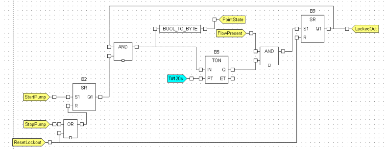
The following function block diagram is an example of a Logic program that could be used as a safety interlock for controlling a pump. It is used to control a pump - the pump cannot be started when there is no flow. This is achieved by establishing these relationships:
- When a ‘StartPump’ signal is sent, the pump motor starts. However, if a flow has not been detected after a 120 second period, the pump is stopped and locked out (the pump stops responding to controls).
- When a ‘StopPump’ signal is sent, the pump motor stops running.
- When a ‘ResetPump’ signal is sent, the pump is no longer locked out. A ‘StartPump’ signal can be sent to the pump to attempt to start it, but if a flow is not detected within 120 seconds, the pump will be locked out again.

As you can see, the ‘LockedOut’ output is also used as an input for an AND function. This means there is a ‘feedback loop’.
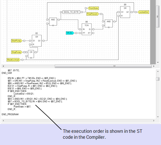
Engineers can view the execution order by running the Compile with Diagnostics tool. This displays the function block diagram as ST code in the compiler, and lists the order in which the various elements of the program are executed.

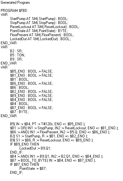
The Compile with Diagnostics feature is selected and it shows the ST that Geo SCADA Expert has generated for the Function Block Diagram. The execution order is clearly shown in the ST code, with the code being executed from top to bottom:

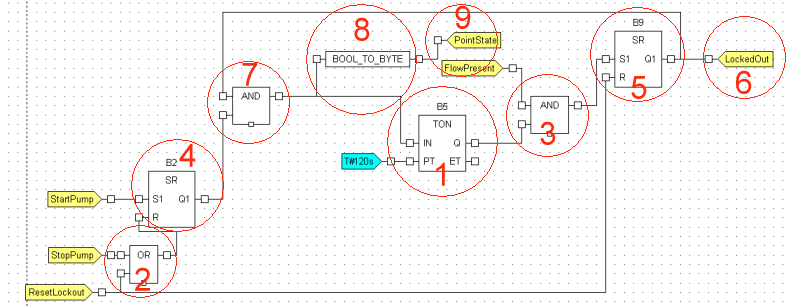
By analyzing the ST that has been generated for the Function Block Diagram, we can see that the execution order is as follows:

Geo SCADA Expert executes the elements to produce the ‘LockedOut’ output/input first, and then executes the elements required to produce the ‘PointState’ output.