You can create a new shape on a Mimic by combining the polylines of multiple Mimic objects. For example, you can create a new shape by combining the polylines of a rectangle and a circle. The new shape can then be edited in the same way as any other Mimic object.
There are 2 methods that control how a combined polygon is filled:
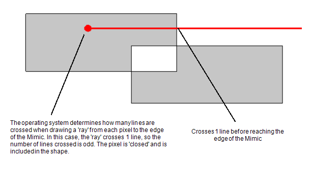
- Even-Odd—The operating system determines whether each pixel of the shape should be 'filled' or 'open'. To do this, it counts the number of lines between each pixel and the edge of the Mimic. If the number is even, the pixel is included in the shape and is 'filled'; if the number is odd, the pixel is excluded from the shape and is 'open'.
Example:
Two rectangles are set to overlap.
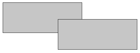
The Fill Mode is set to Even-Odd and the rectangles are combined by using the Combine Polylines action. The rectangles are combined to create the following shape:
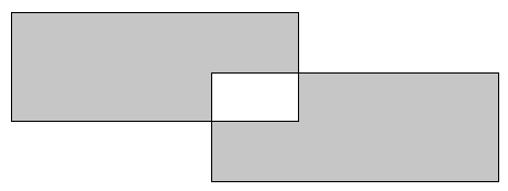
The space where the rectangles overlapped is 'open' (not filled). To determine this, the operating system counted the number of lines crossed when drawing a 'ray' from each pixel to the edge of the Mimic. As the 'rays' for each pixel in the overlapping area cross an even number of lines, the area is 'open'.
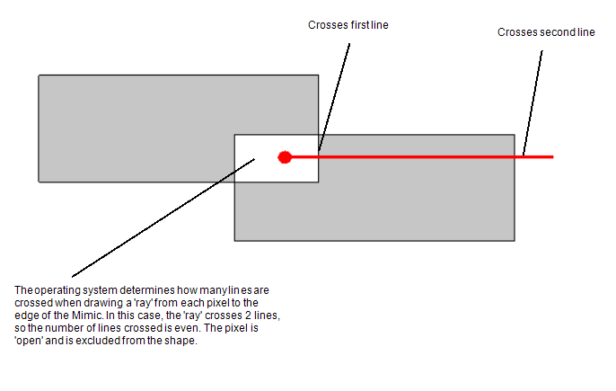
The areas that do not overlap are included in the shape. The operating system determines this in the same way, by counting the number of lines crossed when drawing a 'ray' from each pixel to the edge of the Mimic. As the number is odd, the pixels are included in the shape.
- Non-Zero—The operating system determines whether each pixel of the shape should be 'filled' or 'open'. To do this, it draws a 'ray' from each pixel to the edge of the Mimic. Each time the 'ray' crosses the line of a shape, it adds or subtracts one from a total:
- If the 'ray' crosses the line of a shape that was drawn in a clockwise direction, 1 is added to the total.
- If the 'ray' crosses the line of a shape that was drawn in an anti-clockwise direction, 1 is deducted from the total.
If the final total is zero, the pixel is not included in the shape. If the final total is any number other than zero, the pixel is included in the shape.
Example:
Two rectangles are set to overlap.

The Fill Mode is set to Non-Zero and the rectangles are combined by using the Combine Polylines action. The rectangles are combined to create the following shape:
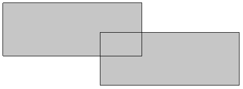
The space where the rectangles overlapped is 'filled'. To determine this, the operating system counted the number of lines crossed when drawing a 'ray' from each pixel to the edge of the Mimic. Each time the 'ray' crossed a line that was drawn in a clockwise direction, the operating system added 1 to the total. Each time the 'ray' crossed a line that was drawn in an anti-clockwise direction, the operating system deducted 1 from the total.
As the total number for the pixels in the overlapping area was not zero, the pixels are included in the shape.
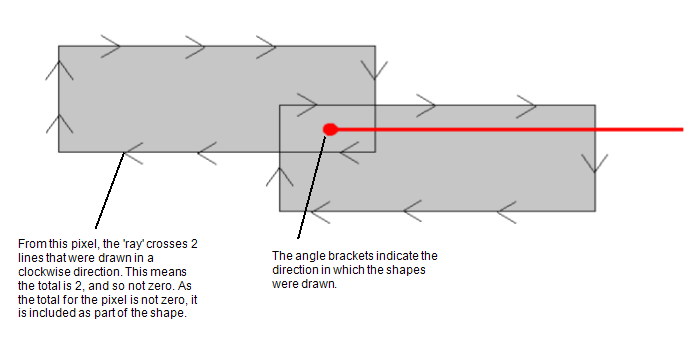
Shapes in Geo SCADA Expert are usually drawn in a clockwise direction. However, you can use the Line tool and the Polygon tool to draw shapes in an anti-clockwise direction if required.
The Fill Mode is mainly used when combining shapes and is also used internally when importing Third Party graphics such as SVG files. However, the same methodology is used when determining the fill for a complex polyline that you have drawn manually—the areas between the lines will be 'filled' or left 'open' according to the Fill Mode setting and the number of lines that are crossed by the 'ray'.
To define the fill mode and combine multiple objects on a Mimic:
- Display the relevant Mimic in Design mode (see Displaying a Mimic).
- Select the objects that you want to combine by either:
- Holding down a Ctrl key and left-clicking on each shape
Or:
- Positioning the cursor on an empty area of the Mimic, then with the left-hand mouse button pressed down, drag the cursor so that it draws a selection box over the objects you want to select. Release the mouse button to select the objects in the selection box.

- Right-click to display a context sensitive menu, then select the Combine Polylines option.
The shapes are combined into a single shape. By default, the shape uses the Even-Odd Fill Mode. - Right-click to display a context sensitive menu, then select the Properties option to display the Multiple Selection Properties window.
- On the General tab of the Multiple Selection Properties window, use the Fill Mode combo box to select Even-Odd or Non-Zero as required.
- Close the Multiple Selection Properties window.
- Select the objects to be included in the shape again (see step 2).
When you combine shapes, the resulting shape will use the Fill properties of the uppermost object in the selection (the object that is 'top' in the z order, that is, is layered above the other objects or was created before the other objects).