In Geo SCADA Expert, there are two different categories of database point: internal database points and 'normal' database points. Of course, within these categories there are many different types of point, for example, 'normal' database points include analog and digital points for each different driver.
- 'Normal' database points are used to represent real I/O. For example, database points can represent inputs from and outputs to plant such as sensors, valves, and so on.
- Internal database points are different as they are not used to represent actual I/O from an external source. Instead, they are used to represent and store values that are only used internally within Geo SCADA Expert.
As you are only just starting out with point configuration, we are going to show you how to:
- Create an internal analog point.
- Configure the internal analog point so that it has the Historic feature enabled. This means that Geo SCADA Expert will keep a record of the internal point’s values.
When you have created the internal analog point, you will learn how to display its value on a Mimic, control its value, and view its values on a Trend. This will help you to understand how items are configured and information can be displayed in Geo SCADA Expert.
To add an internal analog point and enable its Historic feature:
- Right-click on the 'MyFirstTest' Group and select Create New>Internal>Analog Point. This will create a new internal analog point in the 'MyFirstTest' Group. The internal analog point is selected automatically, ready for you to define its name.
- Name the internal analog point:
InternalWaterLevel
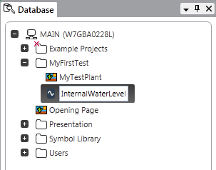
For this exercise, we are going to use the internal analog point to represent the I/O for an imaginary water level sensor (as used in the water industry). On a 'live' system, a 'normal' analog point would be used and it would represent the I/O from a real water level sensor installed in, for example, a reservoir, or tank.
- Display the configuration Form for the 'InternalWaterLevel' point by either double-clicking on the point on the Database Bar or by right-clicking on the point and then selecting Edit Properties from its context sensitive menu.
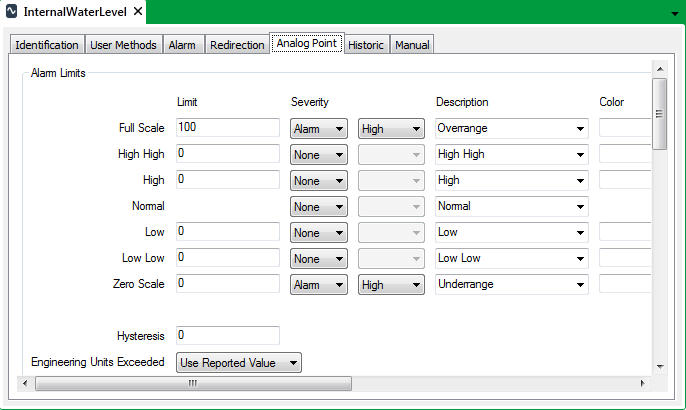
The configuration Form consists of several tabs, each containing a variety of settings. The tabs are shown across the top of the Form, and if you select one, different settings are shown. These tabs are common to many points, but other types of database item have different tabs, for example, a Logic program’s configuration Form only has Identification, User Methods and Logic tabs.
Before you proceed with the next step, take a moment to select the different tabs and look at the settings that are available.
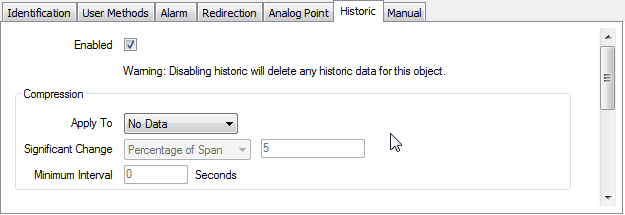
- Select the Historic tab. This tab contains the settings that relate to the internal point’s historic data (the record of past values).
- Select the Enabled check box to turn on the historic feature for the internal point. As soon as you save the Form, the values for the internal point will be stored online (for a specific time period). If a point does not have Historic enabled, it means that you can only access its current value and state.
- In the Trend/List section, select the browse button next to the Offset field. This displays an Offset dialog box.
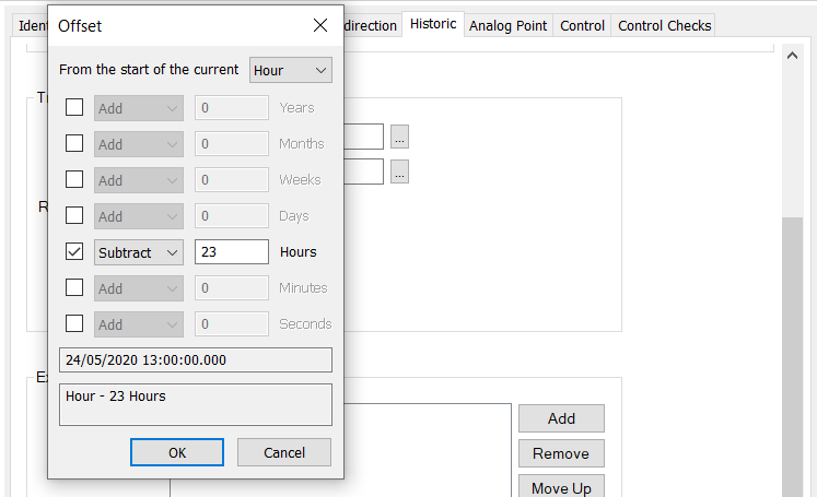
- Use the Offset dialog box to define the start time of the Interval that will be shown on Historic Trends and Historic Lists for the point. The Interval is the time span that is visible on the X-Axis.
- Change the From the Start of the Current setting from Hour to Minute. This instructs Geo SCADA Expert to calculate the Offset from the beginning of the current minute, rather than the beginning of the current hour.
- Clear the check box next to the default setting of Subtract 23 Hours. This removes the existing Offset which is in hours.
- Select the check box for the Minutes row, and change Add to Subtract and the 0 to 5. This means that when you display an ad hoc Historic Trend for the point, the Interval will start 5 minutes before the start of the current minute. So if you displayed the Historic Trace at 10:30:00, the Historic Trace’s Interval would begin at 10:25:00.
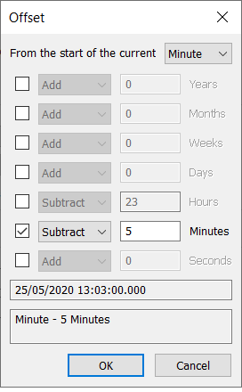
- Select the OK button to confirm your choices and close the Offset dialog box.
- Select the browse button next to the Interval field. This displays an Interval dialog box.
- Use the Interval dialog box to define the length of time that is visible on the X-Axis by default. For this tutorial, disable the default setting of Add 1 Days and define a setting of Add 10 Minutes. This means that when you display an ad hoc Historic Trend for the point, the X-Axis will represent 10 minutes, with the first time shown on the X-Axis being 5 minutes before the start of the current minute (as defined by the Offset).
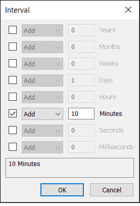
- Select the OK button to confirm your choices and close the Interval dialog box.
- Save the configuration changes. Either:
- Select the File menu.
- Select Save command from the relevant command group.
Or:
- Select the Save button
 on the Quick Access Toolbar.
Or:
- Press the Ctrl and S keys simultaneously.
- Close the internal analog point’s Form.
You’ve now created an internal analog point, configured it to have historic data and defined the settings for the point’s Historic Trend and Historic List. Next, you will Use Drag and Drop to Display the Point Data on a Mimic.
Further Information
Internal Points: see Internal Points.