Each client - system connection is allocated a cost number that is used by the system to determine the order of preference for the connections—the connection with the lowest cost is the preferred connection. Usually, the cost indicates the efficiency of the connection, with the more efficient connections having the lowest cost numbers.
When a client connects to a server, it automatically connects to the server that has the lowest Node Cost value and is available. This sets the client to use the most suitable route to the system. If there are two connections that have the same Node Cost, the client will connect to the server that is Main.
To define the Node Cost for a client - system connection, you need to have an appreciation of the type and efficiency of each connection:
- If the connections are via a Local Area Network (LAN), you should set the Node Cost of each connection to the same amount. This means that a client only connects to the Main server.
- If there are Wide Area Network (WAN) connections, you should set the Node Cost to indicate the amount of bandwidth that is available for the connection. The connections that provide the lowest amount of bandwidth are the least efficient and so should have the highest Node Cost values.
You can use any numbers to define the Node Costs, but the lowest number in your chosen range must be allocated to the connection that provides the most suitable route to the server. You can allocate subsequent numbers to the next most efficient connection (the least efficient connection will have the highest number in the range). For more information on how the Node Cost settings are used, please refer to the examples at the end of this section.
To define the Node Cost for a client - system connection:
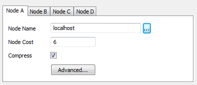
- Display the Client Configuration Window for the connection that you want to add or edit.
- Select the tab for the Node that you want to configure.
- Use the Node Cost field to define the cost. The cost is used to define the relative efficiency of each connection. You can enter any number, but remember that the number will be used as part of range and will be compared to the Node Cost numbers of any other connections
 .
. - Select the OK button to confirm your selections and close the Client Configuration window.
You can also define the Cost setting by editing the Systems.xml file manually Use the Systems.xml File to Set Up a ViewX Client Connection.
Examples of Node Costs:
Hot-Standby Pair Connected via a Wide Area Network (WAN)
A system has a client connected to one server via a Local Area Network connection (LAN) and to the alternate server via a Wide Area Network connection (WAN). The LAN connection is the preferred connection as it is local and is not restricted by the available bandwidth.
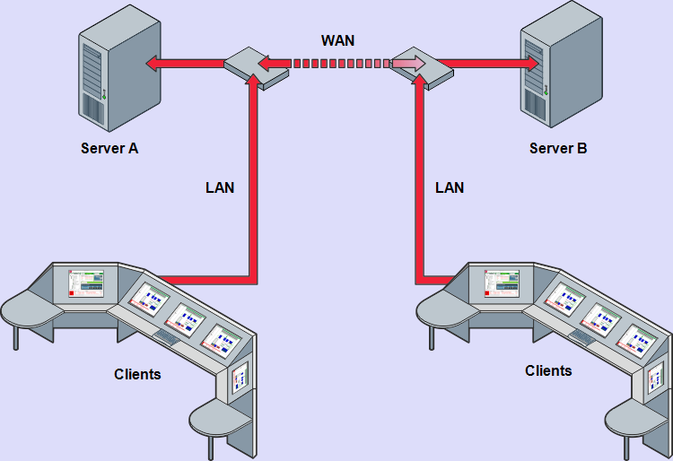
In the diagram above, there are two clients. One client is connected to server A via a LAN and to server B via a WAN. The other client is connected to server B via a LAN and server A via a WAN.
For the client with a LAN connection to server A, the LAN connection has a cost of 2. The connection to server B has a cost of 3—the cost is higher as it is not the preferred connection. When the client is started, it will attempt to connect to server A via the LAN in preference to connecting to server B via the WAN.
For the client with a LAN connection to server B, the LAN connection has a cost of 2. The connection to server A has a cost of 3—the cost is higher as it is not the preferred connection. When the client is started, it will attempt to connect to server B via the LAN in preference to connecting to server A via the WAN.
Hot-Standby Pair with Permanent Standby Arrangement
A system has a client (Client A) connected to a permanent standby server (P.Standby 1) and a server (Server A) via a Local Area Network (LAN). The client is also connected to another server (Server B) via a Wide Area Network (WAN).
Another client (Client B) is connected to Server B and a different permanent standby server (P.Standby 2) via a LAN. Client B is also connected to Server A via a WAN.
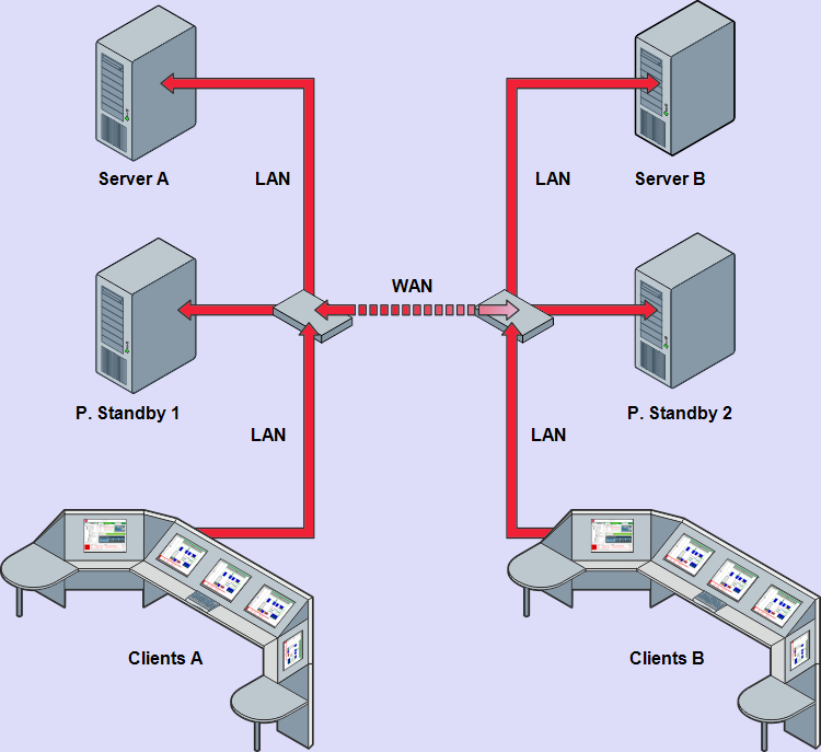
For Client A, the preferred connection is to P.Standby 1 as this reduces the load on Server A. The connection to P.Standby 1 has the lowest cost (cost 1). The Server A connection has the next lowest cost as it should be used in preference to the WAN connection, but not in preference to the P.Standby 1 connection.
For Client B, the preferred connection is to P.Standby 2 as this reduces the load on Server B. The connection to the P.Standby 2 has the lowest cost (cost 1). The Server B connection has the next lowest cost as it should be used in preference to the WAN connection, but not in preference to the P.Standby 2 connection.
Dual Ethernet Hot-Standby Pair Arrangement
A Hot-Standby Pair arrangement has both servers connected via a dual Ethernet network. This provides redundancy in the event of a network failure.
The cost settings for the systems vary depending on the amount of bandwidth available.
For symmetrical networks (networks with the same amount of bandwidth available), the cost should be equal i.e. both connections should have the same cost settings.
For asymmetrical networks (where one network has more bandwidth available than the other), the network with the most bandwidth available should have the lowest cost setting.
The diagram below shows how the cost settings for an asymmetrical dual Ethernet network could be configured.
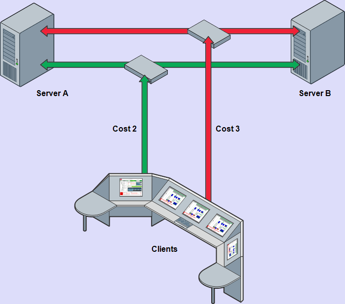
The network with a cost of 2 is used in preference to the network with a cost of 3.
Triple Standby Arrangement
The Cost settings for connections to servers in a triple standby arrangement are dependent on the types of connection.
For a triple standby arrangement where the clients connect to the servers via a Local Area Network (LAN), the cost settings for each system are the same. This sets the clients to only connect to the server that is Main.
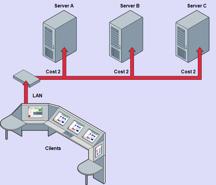
If the clients are connected to Server A or B via a Wide Area Network (WAN), the WAN connection will have a higher cost than the other connections. As a result, the LAN connections are used in preference to the WAN connection.