You can adjust the display settings of graphical Logic Programs. This includes the following program types:
- Ladder Diagrams
- Function Block Diagrams
- Function Block Libraries
- Sequential Function Charts.
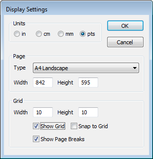
The display settings allow you to adjust the size and orientation of the page on which a program is displayed. You can also display a grid on the page to assist with the alignment of objects, and enable the Snap to Grid feature.
To adjust the display settings for a graphical Logic Program:
- Display the Logic Program.
- Select the Logic tab on the ViewX ribbon.
- Select theDisplay Settingscommand in the View command group.
The Display Settings dialog appears.
- Select the Units of measurement that you would like to use for the fields on the Display Settings dialog.
- In the Page section, select the page Type (based on a standard size and orientation), or define a custom size using the Width and Height fields.
- In the Grid section, use the Width and Height fields specify the dimensions of the grid intervals.
- To display the grid, select the Show Grid check box. Clear the check box to hide the grid.
- To allow objects on the page to automatically align with the grid, select the Snap to Grid check box. Clear the check box to disable the Snap to Grid feature.
- To display the boundaries of a page, select the Show Page Breaks check box. This is useful if a diagram extends beyond the dimensions of a single page. Clear the check box to hide the page breaks.
The display settings for a Logic program are configured independently for Design mode and Run mode.
Further Information