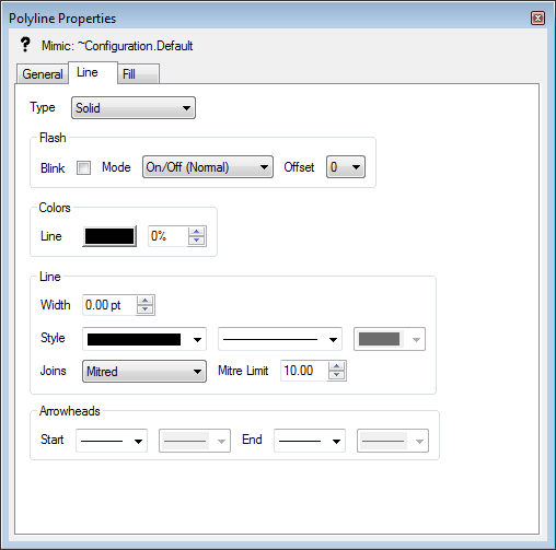
The Line tab contains the settings you need to define the appearance of lines and outlines (the lines around shapes).

- Type—You can choose between two types of line:
- None—The outline of the selected object on the Mimic is not shown.
- Solid—The outline of selected object on the Mimic is a visible line of a single color.
- Flash—The Flash section contains a Blink check box, a Mode combo box, and an Offset combo box. These settings work in exactly the same way as the Flash settings on the Fill tab (see Fill Tab), except that they apply to the outline of an object rather than its fill.
- Colors—Use the Colors section to define the color of the outline or line.
- Line—Use the Line color button to define the color of the line or outline. As with other color buttons, when you select the color button, a color palette is displayed. You can choose a color from the palette, or you can select the ... option to create a custom color (see Using the Color Window).
- % (Transparency)—Use the percentage spin-box next to the Line color button to define the transparency of the color. You can set the color to have a minimum 0% transparency (solid) up to a maximum transparency of 100% transparency (invisible).
- Line—Use the settings in the Line section to define the appearance of the line:
- Width—Use the Width spin-box to increase or decrease the thickness of the line or outline. The width is measured in points (the same measurement is used for font sizes when adding text).
- Style—Use the three Style combo boxes to choose the type of line or outline. The left-hand combo box allows you to choose from a variety of single and double line styles, and the middle combo box allows you to choose continuous or dashed style lines. If you select a dashed line, you can use the third combo box to choose the types of dashes (squared, rounded, or mitered).
- Joins—Use the Joins combo box to define the appearance of corners (joins) on the outline. You can choose from:
- Mitred—The joins are pointed.
- Rounded—The joins are curved.
- Beveled—The joins are angled.
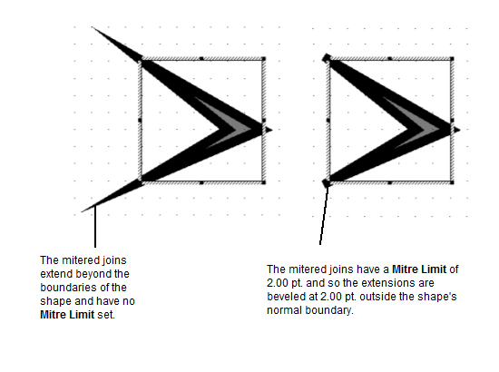
- Mitre Limit—Use to define the limit for mitered joins. The limit is measured in points.
Acute-angled mitered joins can extend beyond the normal boundaries of a line or shape. This can make certain shapes and lines seem inappropriately sized, especially when the line width is set to be thick. By defining a Mitre Limit, you can restrict the mitered joins so that they can only extend so far. At the position where the mitered join reaches the limit, Geo SCADA Expert will set the join to be beveled.

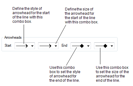
- Arrowheads—Use the Arrowheads section to define the appearance of each end of a line:
- Start—The Start of the line is the left-hand end or top end of the line. Choose the required style of arrowhead from the Start combo box list, and the size of arrowhead from the combo box that is shown to the right of the Start combo box.
- End—The End of the line is the right-hand end or bottom end of the line. Choose the required style of arrowhead from the End combo box list, and the size of arrowhead from the combo box that is shown to the right of the End combo box.
