Configure Modbus Point Scanner Configuration
The Configuration section allows you to configure the general point scanning properties.
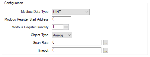
Modbus Data Type
Use this combo box to specify the format of the point value. Select from the following:
Discrete
The value is formatted as a discrete number (binary points only)
INT
The value is formatted as signed 16-bit data. Each INT comprises 1 Modbus register.
UINT
The value is formatted as unsigned 16-bit data. Each UNIT comprises 1 Modbus register.
DINT
The value is formatted as signed 32-bit data. Each DINT comprises 2 Modbus registers (analog points only)
UDINT
The value is formatted as unsigned 32-bit data. Each UDINT comprises 2 Modbus registers (analog points only)
Real
The value is formatted as an IEEE 32-bit single-precision floating point value. Each REAL comprises 2 Modbus registers (analog points only).
Enter the first address in the Modbus register range that you want scanned.
The valid range depends on the Modbus data type:
1 to 9999 or 10001 to 19999
30001 to 39999 or 40001 to 49999
Enter the total number of Modbus registers that you want to be scanned and mapped.
This parameter is only configurable after a valid Modbus Register Start Address is entered. It is automatically updated based on the Modbus Data Type. For example, DINT and REAL data types require twice as many Modbus Registers as UINT or INT data types
Scan Rate
Enter the frequency rate at which the SCADAPack x70 scans the point. Enter the rate directly in the field (see Specify a Time Period in the OPC Time Format) or use the Interval Window to specify the rate that you require, (see Configure Modbus Slave Device Configuration Settings)
To use the same scan rate as the Modbus Slave, leave the default setting of 0.
Timeout
Use this check box to set the amount of time that the SCADAPack x70 should wait for a response when it scans the point on the Modbus Slave device. To use the same timeout as the Modbus Slave, leave the default setting of 0.
If the SCADAPack x70 does not get a response in this time, it will try the scan again until it exceeds the Maximum Consecutive Timeouts count. If the SCADAPack x70 still cannot get a response after the retries, it will determine that it cannot communicate with the device, (see Configure Modbus Slave Device Configuration Settings).
Enter the required interval in the OPC Time Format. You can enter the value directly in the field, or use the Interval window (accessed via the field's browse button) to specify the required value.
The timeout value that you enter is for each scan.