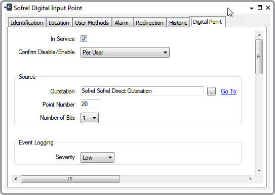
Configure Common Digital Point Properties
Use the fields at the top of the Digital Point tab to Configure Common Point Properties. Fields that are specific to digital points are explained below.
Use to specify whether a point is active or inactive (see Placing an Item In Service).
Users with the required permissions can disable a point that is In Service, or enable a point that is not In Service. Such actions are carried out using the Disable Point and Enable Point pick actions.
Use the Confirm Disable/Enable combo box to specify whether a confirmation dialog box is displayed whenever an operator requests that this point is disabled or enabled (see Requesting Confirmation of Action Requests).
Source Section
The source section allows you to identify the location and reference number of the point.
Use to specify the outstation on which a point is located. Use the browse button to display a Reference browse window and select the relevant outstation from the window.
Enter the pointer number that references the point in the outstation. The protocol configured in the outstation determines the range of the point numbers that you can use to enter in this field:
- LACBUS-RTU protocol: You can use any number from 1 to 4095 to uniquely identify a point.
- SOFBUS-PL protocol: You can use any number from 1 to 1000 to uniquely identify a point. Each of five point types has a separate block, a 1000 of each type: AI (Analog Input), AO (Analog Output), DI (Digital Input), DO (Digital Output), CI (Counter Input).
The point number must match the point number previously configured in the outstation using the Sofrel Configuration application (SOFTOOLS). If you import or upload (LACBUS-RTU only) the configuration, these numbers are inserted automatically.
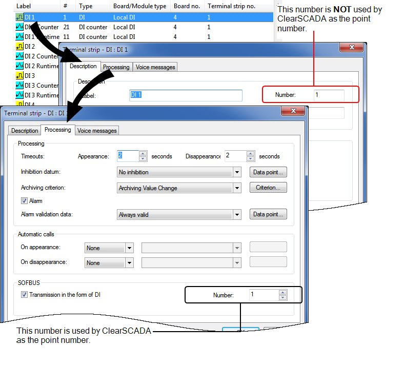
When an S500 outstation is configured to use the SOFBUS-PL protocol you should refer to the configuration information within SOFTOOLS to determine the point number that you should use.
This example illustrates the configuration of points within an S500 outstation using the SOFBUS-PL protocol. Each point has a description number, which is unique to the outstation, but is NOT used within ClearSCADA. In addition each point has a Processing number, which can be any number from 1 to 1000 for a point type.
The Processing number is used by ClearSCADA as the point number.
Use this combo box to specify the number of bits for the point. This corresponds to the number of consecutive 1-bit points that form the point.
The number of bits directly affects the number of point states (see Point State Properties). For further information, see Single and Multi-Bit Digital Points.
Event Logging Section
Use this combo box to define the severity of any non-state events or alarms for the point. For more information on severities, see Defining Severities.
This field is only displayed if the Area of Interest feature is enabled on your system. Use the field to specify the Area of Interest with which any non-state related point alarms or events are to be associated (see Assign a Different Area of Interest to an Item’s Alarms and Events).