Some analog points have different types of alarm limit to those mentioned in this guide. For example, the range supported by some analog points is Underrange to Overrange, rather than Zero Scale to Full Scale. The Procedure for Configuring an Analog Point’s Limits is typically similar, regardless of the type of limit. The driver guides explain any limits and configuration differences that are driver-specific.
You need to set the limits for each analog point so that when the value of the point drops below or rises above the normal range of values, a suitable alarm is raised or event is logged. The value of the point is retrieved from the outstation.
To configure the limits of an analog point, you need to access the Analog Point tab of the relevant type of Analog Point Form.

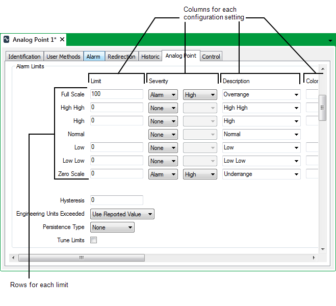
The Alarm Limits section has a row of fields for each limit. The fields are arranged in columns, and are used for defining the configuration properties of each limit (see Procedure for Configuring an Analog Point’s Limits). The figure above shows the types of limit that are available for analog points on many drivers. Some analog points have different limits to those shown above (see Analog Points with Different Limits).
Zero Scale and Full Scale define the range of values (in engineering units) for a point. The values that you enter for these limits have to correspond with the raw scale of the point in the outstation. Most drivers use these values to scale the raw values that are reported by the outstation.
Example:
A raw scale of 0 to 4095 (12-bit) might be configured on the Point Form as:
Zero Scale = 0 (corresponding to the raw value 0)
Full Scale = 10 (corresponding to the raw value 4095).
Use the other Limit fields to define limits between the Zero Scale and Full Scale that indicate notable changes in operating condition of the plant. By default, the alarm limits are High High, High, Low, and Low Low for analog points on most drivers. You can specify whether a point passing one of these limits raises an event or an alarm. (With analog points on some drivers, you can optionally assign these limits to Time Profiles, to enable the limits’ values to change at different times of the day or week (see Specify any Alarm Limit Profiles).)
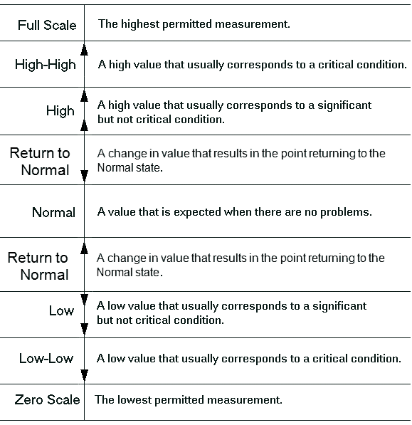
The Normal state defines the usual operating range for the plant. If supported by the point, you can choose whether to log an event or raise a fleeting alarm whenever the point to returns to this state. The Normal state operating range falls between those alarm limits that are immediately adjacent to the Normal state (typically the operating range that is between the High and Low alarm limits).
The range of limits forms a scale, as follows:

Example:
An analog point has this configuration:
Full Scale: 24 (Alarm)
High High: 22 (Alarm)
High: 20 (Event)
Normal (None)
Low: 4 (Event)
Low Low: 2 (Alarm)
Zero Scale: 0 (Alarm).
The configuration indicates that the full operating range of the point is 0-24, but that the normal operating range is between 4 and 20.
From normal operating conditions, if the point value falls to 4 or below, an event is raised. If the value continues to drop to 2 or below, an alarm is raised. The existing alarm is replaced by another alarm should the point reach its lowest operating range of 0.
Similarly, from normal operating conditions, if the point value rises to 20 or above, an event is raised. If the value continues to rise to 22 or above, an alarm is raised. The existing alarm is replaced by another alarm if the point exceeds its maximum operating range of 24.
Alarms are cleared as the value returns to its normal operating range of between (but not including) 4 and 20. For instance, should the point value drop from 23 to below 22, the High-High alarm clears. If the value then drops below 20, the High alarm clears—the point has now returned to its normal operating range.