Configure the Advanced Trio Diagnostic Properties that are Specific to Analog Points
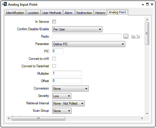
Use the fields on the Analog Point tab to configure the analog input point properties and output point properties that are specific to the Advanced Trio Diagnostics driver. Some of the fields are common to many Advanced Trio Diagnostics points (see Configure the Common Point Properties). Fields that are specific to Advanced Trio Diagnostics Analog Input points and Advanced Trio Diagnostics Analog Output points are explained below.

- Convert to mW—Only applies if the Parameter field is set to RSSI (PIC 6), RSSI Threshold (PIC 76), or one of the Power options.
Select the Convert to mW check box if the value that the driver retrieves is in decibels (dB) and the driver is to convert the value to milliwatts (mW) for use in Geo SCADA Expert.
Clear the check box if conversion is not required.
- Convert to Fahrenheit—Only applies if the Parameter field is set to Internal Temperature ( PIC 3 ).
Select the Convert to Fahrenheit check box if the value that the driver retrieves is in degrees Celsius and the driver is to convert the value to Fahrenheit for use in Geo SCADA Expert.
Clear the check box if conversion is not required.
- Multiplier—Only applies if the Parameter field is set to Define PIC. Use the Multiplier field to specify the amount by which the Advanced Trio Diagnostics driver is to multiply each diagnostic value that it retrieves from the radio, before passing the resultant value to Geo SCADA Expert. Trio radios other than D Series tend to return diagnostic values as fixed point integer values that you might want to scale by a suitable power of 10 (such as 0.01, 0.1, 1, 10, or 100) for use in the Geo SCADA Expert database; you do so using the Multiplier field.
Leave at the default of 1 if you do not want the driver to apply a different multiplier.
- Offset—Only applies if the Parameter field is set to Define PIC. Specify the amount that the driver should add or subtract from each diagnostic value that it retrieves from the radio, once it has applied the Multiplier, to produce an engineering value (the value that Geo SCADA Expert uses in the database). Leave at the default of 0 if you do not want to apply an offset (you would typically leave the Offset at this default value for most series of Trio radio).
You might set the Multiplier to 0.1 and the Offset to 5.
Geo SCADA Expert applies this scaling to produce an engineering value. (An engineering value is the value that is used in the database, in place of the raw value that was retrieved from the radio).
For example, to scale a value of 45, the driver multiplies this value by 0.1, then adds 5 to the value (that is, (45 x 0.1) + 5 = 9.5). It then stores the result (that is, 9.5) in the database.
- Conversion—Only applies if the Parameter field is set to Define PIC. Use the Conversion combo box to indicate whether the driver needs to convert each retrieved diagnostics value before passing the value onto Geo SCADA Expert.
Choose from:
- None—No conversion is required. This is the default option.
- dBm to mW—Select this option if the retrieved values are power ratios in decibels (dB) and the driver is to convert those values to milliwatts (mW) for use in Geo SCADA Expert.
- mW to dBm—Select this option if the retrieved values are in milliwatts (mW) and the driver is to convert those values to decibels (dB) for use in Geo SCADA Expert.
- Celsius to Fahrenheit—Select this option if the retrieved values are temperatures measured in degrees Celsius, which the driver is to convert to degrees Fahrenheit for use in Geo SCADA Expert.
- Severity—Use this combo box to define the severity of any non-state events or alarms for the point. For more information on severities, see Defining Severities in the Geo SCADA Expert Guide to Core Configuration.
- Area of Interest—This field is only displayed if the Area of Interest feature is enabled on your system. Use the field to specify the Area of Interest with which any non-state related point alarms or events are to be associated (see Assign a Different Area of Interest to an Item's Alarms and Events).
Further Information
Persistence: see Use Persistence to Stop Fleeting Changes in Value from Changing a Point State.
The other properties on the Analog Point tab that are not shown in the above figure are common to analog points on many drivers. For information on the fields, see Defining Analog Point Details in the Geo SCADA Expert Guide to Core Point Configuration.