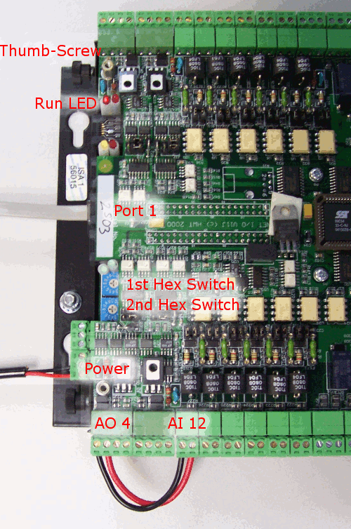
The figure below shows a typical SCADAPack ES outstation with the cover removed.

In order to successfully complete this Quick Start Tutorial, you need to perform the following actions to prepare the SCADAPack ES outstation:
- Use two lengths of insulated copper wire to connect analog output 4 of the SCADAPack ES outstation to analog input 12.
Make sure you match the +ve and -ve terminals.
- Connect the Geo SCADA Expert server to Port 1 of the SCADAPack ES outstation using the RS-232 9-Pin D-Sub to the RJ12 Serial Cable.
- Unscrew the four thumb-screws and remove the casing of the SCADAPack ES outstation.
- Put the SCADAPack ES outstation in FC mode. Set the first hex switch to F and the 2nd hex switch to C. (When a new SCADAPack ES outstation is shipped, it will usually be shipped in FC mode.)
- Power up the SCADAPack ES outstation.
- Wait until the SCADAPack ES outstation has completed its start-up sequence. You can monitor the start-up sequence by watching the Run LED. At the end of the start-up sequence, the Run LED will flash rapidly for about one second and then start flashing steadily at one-and-a-half seconds on, one-and-a-half seconds off.
- Remove power to the SCADAPack ES outstation.
- Put the SCADAPack ES outstation in 00 mode (both hex switches in the 0 position).
- Do not power up the SCADAPack ES outstation yet.
For more information on setting up a SCADAPack ES outstation, refer to the SCADAPack ES product documentation.
Now Create the Geo SCADA Expert Database Items that you require for this tutorial.