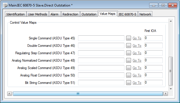
Use the fields within the Control Value Maps section of the Value Maps tab to specify the Filtered Value Maps that store the output data for this slave outstation. The Filtered Value Maps that store a slave outstation’s data have to exist on your system before you can use the fields below to map to such data. (For more information, see Specify the Filtered Value Maps that Store the Source Data, and see Configuring Value Maps in the Geo SCADA Expert Guide to Core Configuration.)

- Single Command (ASDU Type 45)—Specify the Filtered Value Map that is used to store single-bit output values. Use the browse button to display a Reference browse window and select the required Filtered BIT Value Map from the window.
- Double Command (ASDU Type 46)—Specify the Filtered Value Map that is used to store 2-bit output values. A Double Command is typically used for a switch or valve, with state 1 representing the ‘Off’ state and state 2 the ‘On’ state.
- Use the browse button to display a Reference browse window and select the required Filtered BYTE Value Map from the window.
- Regulating Step Command (ASDU Type 47)—Specify the Filtered Value Map that is used to store 2-bit output step values. A Regulating Step Command is typically used to step up or down a transformer, with state 1 typically being used to represent ‘Next Step Lower’ and state 2 ‘Next Step Higher’.
- Use the browse button to display a Reference browse window and select the required Filtered BYTE Value Map from the window.
- Analog Normalized Command (ASDU Type 48)—Specify the Filtered Value Map that is used to store ‘normalized’ analog output values (values that are restricted to the range -1 to +1). Use the browse button to display a Reference browse window and select the required Filtered REAL Value Map from the window.
- Analog Scaled Command (ASDU Type 49)—Specify the Filtered Value Map that is used to store scaled analog output values (values that are in the range -32678 to +32767). Use the browse button to display a Reference browse window and select the required Filtered DINT Value Map from the window.
- Analog Float Command (ASDU Type 50)—Specify the Filtered Value Map that is used to store IEEE single-precision (32-bit) floating point output values. Use the browse button to display a Reference browse window and select the required Filtered REAL Value Map from the window.
- Bit String Command (ASDU Type 51)—Specify the Filtered Value Map that is used to store 32-bit string output values. Use the browse button to display a Reference browse window and select the required Filtered UDINT Value Map from the window.
Leave the fields blank for any Control Value Map types that are not used by this slave outstation.
The Control Value Maps section also includes fields that you use to specify the:
- First IOA—Each output on a slave outstation has an Information Object Address (IOA). This address is used to uniquely identify each item on the outstation and is transmitted in each ASDU that includes information about that particular output.
- Use the First IOA field adjacent to a Filtered Value Map field to specify the IOA address of the first output on that particular Value Map. In each case, Address 0 on the Filtered Value Map represents the IOA that you specify in the First IOA field for that Value Map; Address 1 represents the next consecutive IOA, and so on.
- For outstations that communicate using the IEC 60870-5-101 protocol, the valid range for this address varies—for more information, see the First IOA field details within Specify the Status Value Maps.