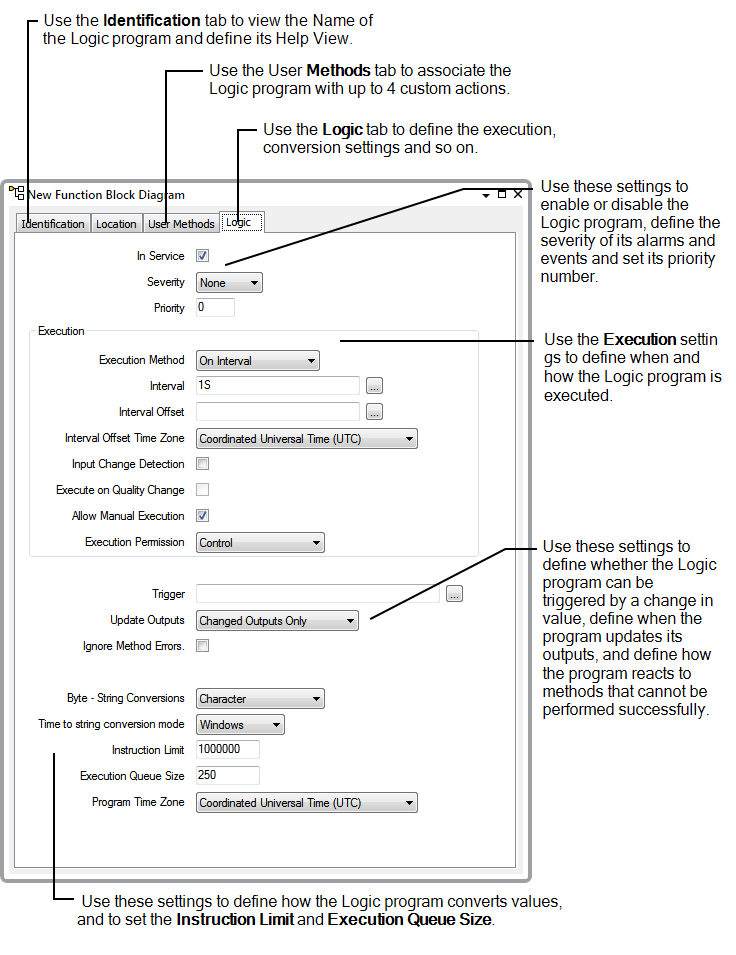
Each Logic database item has its own Form that you can use to configure relevant settings. The Forms for ST Programs, Ladder Diagrams, Sequential Function Charts and Function Block Diagrams are very similar. You can use them to:
- View the Name and configure the Help View for the Logic program. These settings are available on the Identification tab. For more information, see Defining Identification Details in the Geo SCADA Expert Guide to Core Configuration.
- Associate the Logic program with up to 4 custom pick actions by using the User Methods tab. For more information, see Using the User Methods Tab to Define Custom Actions in the Geo SCADA Expert Guide to Core Configuration.
For more information, see the topics that are listed in the gray footer section at the bottom of this topic. Select the relevant entry to display the topic that you require.
To create the code or diagram for a Logic program, you have to use the dedicated Logic editor.
To display a Logic program's Form and configure its settings:
- Display the Database Bar (see Display an Explorer Bar).
- In the Database Bar, right-click on the Logic program icon to display a context sensitive menu.
- Select the Edit Properties option to display the relevant Form.

Alternatively, you can select the Properties option for the program from any instance of the program's context sensitive menu. For example, you may have a Mimic that provides access to an ST Program's Form or to its context sensitive menu.
- Use the Identification tab to define the Help View for the Logic program as required. (see Defining Identification Details in the Geo SCADA Expert Guide to Core Configuration).
- Use the User Methods tab to associate the Logic program with up to 4 custom pick actions as required (see Using the User Methods Tab to Define Custom Actions in the Geo SCADA Expert Guide to Core Configuration).
- Select the Logic tab.
- Use the In Service check box to Enable or Disable the Logic program (see Enable or Disable a Logic Program).
- Use the Severity combo box to set the severity for alarms and events that are associated with the Logic program (see Define the Severity of a Logic Program's Alarms and Events).
- Use the execution-related settings to define when and how the Logic program can be executed (see Define the Execution Settings for a Logic Program):
- Priority—Use to define whether the Logic program is executed in preference to other Logic programs (see Define the Priority of a Logic Program)
- Execution Method—Use to define whether the Logic program is executed on a time basis or when its inputs change (see Define the Execution Method for a Logic Program)
- Interval—Use to define how often timed execution of the Logic program takes place (see Define the Interval Settings for a Logic Program).
- Interval Offset—Use to define the start time for the first timed execution (see Define the Interval Settings for a Logic Program).
- Interval Offset Time Zone—Use to define the time zone to be used when calculating the time for the first timed execution (see Define the Interval Settings for a Logic Program).
- Input Change Detection—Use to define whether the Logic program is executed when it detects a change in the value of one of its inputs (see Define whether a Logic Program Executes when the Value of an Input Changes)
- Execute on Quality Change—Use to define whether the Logic program is executed when it detects a change in the quality of one of its inputs (see Define whether a Logic Program Executes when the Quality of an Input Changes)
- Allow Manual Execution—Use to control the availability of the Execute action that is used to manually execute the Logic program (see Define whether a Logic Program can be Executed Manually)
- Execution Permission—Use to define the permission required to access the Execute action for the Logic program (see Define which Permission is Required to Execute a Logic Program)
- Use the Trigger setting to configure the Logic program to execute in response to a change in the value of a selected property of a specific database item (see Associate the Execution of a Logic Program with a Property in the Database).
- Use the Update Outputs setting to Define when a Logic Program Updates its Outputs.
- Use the Ignore Method Errors setting to Define whether a Logic Program Executes Methods after a Failed Method.
- Use the Byte - String Conversions and String to Time Conversion Mode settings to Define the Conversion Types for a Logic Program.
- Use the Instruction Limit setting to Define the Number of Instructions for a Logic Program.
- Use the Execution Queue Size setting to define the maximum number of values (reported by an outstation) that can be stored in the execution queue. The default setting of 250 is usually appropriate (see Define the Maximum Number of Executions that can be Queued).
- Use the Program Time Zone setting to define the time zone to be used if the Logic program uses time conversion functions (see Define the Time Zone to be used for Calculations within the Logic Program).
- Save the Logic program's Form to confirm and store your selections.