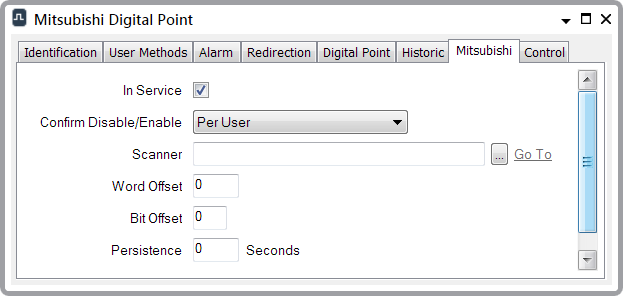
Use the fields on the Mitsubishi tab to configure the Mitsubishi-specific properties for a digital point. Many of the fields on the tab are common to points on many simple drivers—for information, see Configure Common Point Properties in the Geo SCADA Expert Guide to Simple Drivers.

- Word Offset—Use to specify the location of the point data, within the Device address range configured for the scanner. This is the offset into the device, in multiples of 16-bit Words. Specify the value as an offset from the Data Address that is defined on the Scanner Form (see Configure the Scanner Properties). The lowest acceptable offset is zero.
Example:
The Data Address for a Scanner is configured as 8.
The data for a digital point that is attached to the scanner starts at address 14 and so the digital’s Word Offset is configured as 6.
(The Bit Offset field (see below) is used to specify the starting bit within the Word.)For a further example showing how you might configure a Word Offset in conjunction with other configuration properties, see Scan an Internal Relay.
An ‘invalid configuration’ message is generated if the specified Word Offset results in the data location occurring outside of the address range (that is specified for the Scanner).
- Bit Offset—Enter the lowest (starting) bit of the point. With a multi-bit point, the bits have to be consecutive within the file (for example, a 2-bit digital might use bits 5 and 6, where bit 5 would be the starting bit).
The range is 0 to 15.
For an example showing how you might configure a Bit Offset in conjunction with other configuration properties, see Scan an Internal Relay.
- Persistence—Specify the time that the Mitsubishi driver waits before it reports a change of state. Enter the time in seconds. This allows the driver to ignore fleeting changes in point state.