SCADAPack Realflo controllers support ‘standard’ SCADAPack Modbus Analog Input points and Analog Output points (see Points Used on SCADAPack Modbus Realflo Controllers). SCADAPack Modbus Realflo controllers also support SCADAPack Modbus Realflo Analog Input points—points that are used to process flow calculation data in Geo SCADA Expert (see Configure Geo SCADA Expert to Monitor Realflo Calculation Data).
Many items of Flow Run data are available directly from the Flow Run itself—to enable users to view such data, you can attach the Flow Run properties to a display, such as a Mimic, or a Trend. (In such cases, you only need to associate the data with an analog point if you want Geo SCADA Expert to further process or store the Flow Run data—for more information, see View and Process Flow Run Data.)
Some items of Flow Run data are not available directly from the Flow Run database item—they are calculated using the Flow Run’s configuration, but are stored internally. To view or process these items of data in Geo SCADA Expert, you have to configure one SCADAPack Modbus Realflo Analog Input point per item of data to which you require access.
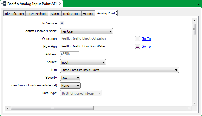
This section summarizes the Realflo-specific properties that apply to SCADAPack Modbus Realflo Analog Input points. You configure these properties using the fields on the Analog Point tab of the SCADAPack Modbus Realflo Analog Input Point Form.

Use the Analog Point tab to:
- Configure the General Realflo Analog Point Properties
- Configure the Alarm Limits (see Configure Alarm Limits in the Geo SCADA Expert Guide to the Advanced Modbus Driver)
- Configure any Alarm Limit Profiles (see Specify any Alarm Limit Profiles in the Geo SCADA Expert Guide to Core Point Configuration)
- Specify the Point Scaling (see Define the Point Scaling in the Geo SCADA Expert Guide to the Advanced Modbus Driver)
- Define the Point Formatting (see Define the Appearance of an Analog Point’s Values in the Geo SCADA Expert Guide to Core Point Configuration)
- Specify the Override Properties (see Define whether an Analog Point can be Overridden in the Geo SCADA Expert Guide to Core Point Configuration)
- Specify the Significant Change Properties (see Define the Criteria for a Significant Change in Value in the Geo SCADA Expert Guide to Core Point Configuration)
- Configure the No Change Properties (see Detect whether an Analog Point has Stopped Changing in the Geo SCADA Expert Guide to Core Point Configuration).
- Specify the Trend Properties (see Define an Analog Point’s Trend Settings in the Geo SCADA Expert Guide to Core Point Configuration)
- Specify the Logged Data Properties (see Log Point Data on SCADAPack Controllers in the Geo SCADA Expert Guide to the SCADAPack Modbus Driver).
The fields on other tabs are common to points on many advanced drivers (see Tabs on Point Forms in the Geo SCADA Expert Guide to Advanced Drivers).