Configure Modbus Slave Device Configuration Settings
The Configuration section of the Modbus tab allows you to specify the settings that enable the SCADAPack x70 to scan the Modbus Slave device.
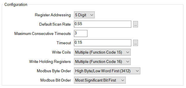
Use this combo box to specify whether the register addresses that the SCADAPack x70 uses to communicate with the Modbus Slave have 5 digits or 6 digits. Be aware that each type of device has its own specific address range—refer to the device documentation for the address range that applies to a specific type of device.
Select the addressing mode that matches the mode used by the Modbus Slave.
| Modbus Data Type | SCADAPack x70 Configuration Type | 5-Digit Address Range | 6-Digit Address Range |
|---|---|---|---|
|
Coil, |
Digital Output Point, Digital Input Point |
1 to 9999 |
1 to 65535 |
|
Discrete Input |
Digital Input Point |
10001 to 19999 |
100001 to 165535 |
|
Input Register |
Analog Input Point, Digital Input Point, Counter Input Point |
30001 to 39999 |
300001 to 365535 |
|
Holding Register |
Analog Output Point, Digital Output Point, Analog Input Point, Digital Input Point, Counter Input Point |
40001 to 49999 |
400001 to 465535 |
The time interval at which the SCADAPack x70 executes the configured scans. The default rate is 0.5 seconds. Enter the required interval in the OPC Time Format. You can enter the value directly in the field, or use the Interval window (accessed via the field's browse button) to specify the required value..
If the Maximum Consecutive Timeouts is exceeded, and the Default Scan Rate is set faster than 15000 ms (15 seconds), the scan rate is automatically slowed to 15 seconds to accommodate the ongoing communications interruptions.
The scan rate returns to the configured Default Scan Rate after the first successful scan and response.
Enter the number of times that the SCADAPack x70 should attempt to send a message to the Modbus Slave before it determines that it cannot communicate with the device.
If the Maximum Consecutive Timeouts is exceeded, and the Default Scan Rate is set faster than 15000 ms (15 seconds), the scan rate is automatically slowed to 15 seconds to accommodate the ongoing communications interruptions.
The amount of time the SCADAPack x70 waits for a reply to a read or write command before considering communications with the device to be interrupted. Enter the required interval in the OPC Time Format. You can enter the value directly in the field, or use the Interval window (accessed via the field's browse button) to specify the required value.
Default value: 100 ms
Use this combo box to select the function code that is supported by the Modbus Slave to be scanned. Select from the following:
This allows multiple coils to be set on or off in a single message. If supported by the Modbus Slave this allow for more efficient communications.
This allows a single coil to be set on or off in a single command. This is less efficient when controlling a block of consecutive coils.
Use this combo box to select the function codes that are supported by the Modbus Slave to write data to holding registers. Select from the following:
Used to write data (2 bytes per register) to a block of contiguous holding registers (1 to 123 registers). If supported by the Modbus Slave this allow for more efficient communications.
Used to write data (2 bytes) to a single holding register. This is less efficient when controlling a block of consecutive registers.
This option impacts on the type of analog data to which the Slave Device's Modbus Point Scanners can write. The option restricts the number of Modbus Data Type options that are available to a Modbus Point Scanner when that Scanner's Operation is set to 'Write' or 'Read/Write' (see Configure the Modbus Scanners Settings).
The order of the bytes sent to a Modbus Slave. Select the byte order and word order combination that matches the order used on the Modbus Slave.
The order you select is used for 32-bit and 16-bit register values, but the second part of the selection — the word order — is not used for 16-bit values because these values consist of just 2 bytes, or 1 word.
- For 32-bit register values, 2 bytes (1 word) are contained in the first register, and 2 bytes (1 word) are contained in the second register.
- For 16-bit register values, the 2 bytes (1 word) are contained in the only register. A second register is not required.
In the setting description, the numbers 1 (Most significant), 2, 3 and 4 (Least significant) represent the 4 bytes in a 32-bit register value and 1 is the most significant byte.
Sends 32-bit values in byte order 3412
Sends16-bit values in byte order 12
Sends 32-bit values in byte order 1234
Sends16-bit values in byte order 12
Sends 32-bit values in byte order 2143
Sends16-bit values in byte order 21
Sends 32-bit values in byte order 4321
Sends 16-bit values in byte order 21
When the Realflo Flow Computer option is selected in the Device Configuration Options section of the Settings tab and the IP Address in the Communication section is set to '127.0.0.1' , the Modbus Byte Order is fixed at 'High Byte/High Word First (1234)'.
This section allows you to define the bit order for register data sent to a Modbus Slave. The bit order selection is applied to every byte that is sent regardless of the byte order. The default settings should only be changed if required.
Select the bit order that matches the order used on the Modbus Slave.
Sends the most significant bit first.
Sends the least significant bit first.