Specify the SCADAPack x70 Device's Point Scaling
The SCADAPack x70 tab on the Forms of SCADAPack x70 Analog Configuration items contains a Scaling section. Use the section to define the scaling that is applied to the analog in the SCADAPack x70 device.
Some features use the analog's raw (integer) value, whereas other features use the analog's scaled engineering (floating point) value. You use the Scaling section of the tab to specify how the two types of value relate to each other.
One particular Analog Configuration item is associated with a physical analog input point. The Scaling section on the item's Form is used to convert the raw values from the measuring instrument with which the analog is associated into suitable engineering values for use in the SCADAPack x70 device. The scaling that is required is determined during the measuring instrument's calibration process.
With analogs for which Geo SCADA Expert is the SCADA master, it is the analog's engineering value (rather than its raw value) that is retrieved for use in Geo SCADA Expert. Conversely, if the analog represents an output point, Geo SCADA Expert uses the Scaling settings to convert the engineering value into a raw value before transmitting that output's value to the SCADAPack x70 device.
The section contains the following properties:
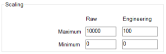
- Maximum and Minimum—Specify the required range for each set of values, to enable the SCADAPack x70 device to scale the raw integer values into engineering values and vice versa.
In the Raw column, enter the uppermost limit for a raw input signal in the Maximum field and the lowest limit for a raw input signal in the Minimum field.
If the analog is associated with a physical analog input or output, use these Raw values to represent the user-defined integer values at the maximum and minimum electrical signals respectively.
With an analog that represents a 4-20 mA channel, you might specify:
- A Raw Maximum value of 10000. With this setting, an integer value of 10000 represents 20 mA
- A Raw Minimum value of 0. With this setting, an integer value of 0 represents 4 mA.
If the analog is not associated with a physical analog input or output, use the Raw values to specify the highest and lowest expected operating integer values for the analog. In which case, the Raw Minimum value can be a negative value.
In the Engineering column, enter the highest valid engineering value in the Maximum field and the lowest valid engineering value in the Minimum field. These values comprise the floating point engineering units values that apply when the analog's value is at the Raw Maximum and Raw Minimum integer values respectively.
In each case, the Maximum value has to be higher than the Minimum value.
The Engineering values are independent of the Overrange and Underrange properties defined in the Out of Range Limits section of the tab. (For details about configuring Overrange and Underrange alarms, see Configure the Out Of Range Limits.)
Further Information