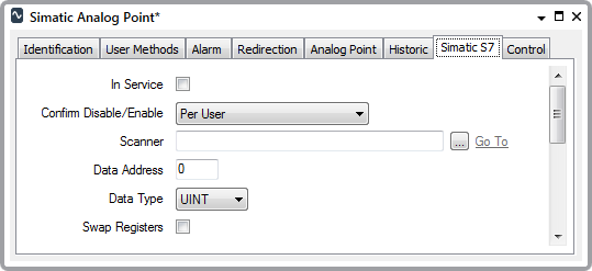
Use the fields at the top of the Simatic S7 tab to configure the Simatic S7-specific point properties. Some of these fields are common to many simple drivers (see Configure Common Point Properties in the Geo SCADA Expert Guide to Simple Drivers). Fields that are specific to analog points on the Simatic S7 driver are explained below:

- Data Address—Specify the address of the register in which the point data is located. The specified address has to be located in the block of registers that the Scanner is configured to scan (see Configure the Scan Properties).
Example:
A scanner scans several analog points on a Simatic S7 PLC.
The scanner has this configuration:
Area: Input Register
Data Address: 10
Data Length: 12One of the analog points has this configuration:
Data Address: 11
Data Type: INT (the data is stored as a 16-bit value)The configuration determines that the scanner scans Input Registers 10 to 21 within the PLC. Within this block of registers, the data for the above analog point is located at registers 11 and 12. (As each register is one byte, the analog data comprises two consecutive registers, starting at register address 11.)
- Data Type—Specify the format of the raw analog data.
Choose from:
- UBYTE—Unsigned 8-bit data. Each UBYTE comprises one Simatic S7 register.
- BYTE—Signed 8-bit data. Each BYTE comprises one Simatic S7 register.
- UINT—Unsigned 16-bit data. Each UINT comprises two Simatic S7 registers.
- INT—Signed 16-bit data. Each INT comprises two Simatic S7 registers.
- UDINT—Unsigned 32-bit data. Each UDINT comprises four Simatic S7 registers.
- DINT—Signed 32-bit data. Each DINT comprises four Simatic S7 registers.
- REAL—IEEE 32-bit single-precision floating point value. Each REAL comprises four Simatic S7 registers.
The byte specified in the Data Address field, above, has to indicate the first byte (or register) of a multi-register point.
- Swap Registers—Applies to Data Types other than UBYTE and BYTE. As this data comprises two or four 8-bit bytes, you can use this check box to specify the order in which the bytes of data are presented in Geo SCADA Expert, and therefore the value that they represent.
Clear the check box if you do not want the data in the registers to be swapped for use in Geo SCADA Expert. For multi-register data, the highest numbered register contains the most significant byte.
Select the check box if the byte values are to be swapped for use in Geo SCADA Expert. For multi-register data, the lowest numbered register contains the most significant byte.
Example:
An analog value has a DINT data type, and is located at registers 16 to 19 in a PLC. The Registers are not swapped.
The present value of the analog is:
Byte 16 = 1
Byte 17 = 0
Byte 18 = 0
Byte 19 = 0As the registers are not swapped, this results in the analog point being given a value of 1 within Geo SCADA Expert.
If the configuration was such that the registers were swapped, this would result in the analog point being given a value of 2147483648 within Geo SCADA Expert.