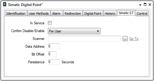
Use the fields on the Simatic S7 tab to define the Simatic S7-specific properties for a digital point. For information on those fields that are common to many simple drivers, see Configure Common Point Properties in the Geo SCADA Expert Guide to Simple Drivers. Fields that are specific to digital points on the Simatic S7 driver are described below:

- Data Address—Specify the address of the register in which the point data is located. The specified address has to be located in the block of registers that the Scanner is configured to scan (see Configure the Scan Properties).
- Bit Offset—Enter the lowest (starting) bit of the point data within the above register. Each register comprises one 8-bit byte. Specify the starting bit as an offset, in the range 0 to 7.
With a multi-bit point, the bits are consecutive. (For example, a 2-bit digital might use bits 5 and 6, where bit 5 would be the starting bit.) The bits of a multi-bit point have to reside consecutively in the same byte in a register range—bits for one point cannot continue into another byte.
- Persistence—Specify the time that the driver waits before it reports a change of state. Enter the time in seconds.
Example:
A scanner scans several digital points on a Simatic S7 PLC.
The scanner has this configuration:
Area: Input Register
Data Address: 10
Data Length: 14
One of the digital points has this configuration:
Number of Bits:2
Data Address: 11
Bit Offset: 5
The configuration determines that the scanner scans registers 10 to 23 within the PLC. In this block of registers, the digital point detailed above is located at register 11, starting at the sixth bit within that register, and continuing to the seventh bit.
To read the value of this point, the scanner extracts bits 6 and 7 of register 11.