Each Mimic object has a General tab on its Properties window.
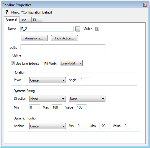
The General tab contains some settings that are object specific - for example, the General tab for a button contains a Button section - and several common settings including:
- Name—The Name field shows the name of the currently selected Mimic object. The name is a reference, such as P_21, that is used internally by ClearSCADA. To change the name, select the browse button next to the name field to display a pop-up window, then enter the new name in the New field.
- Visible—Use the Visible check box to define whether the selected Mimic object can be seen on the Mimic. If you select the check box, the Mimic object can be seen; if you clear the Mimic check box, the Mimic object will not be shown on the Mimic.
- Animations—Use the Animations button to access the Animations window. You need to use the Animations window to associate values in the database with properties of Mimic objects. For information on the Animations feature, see Animations.
- Pick Action—Use the Pick Action button to access the Pick Action Wizard. You can use the Pick Action Wizard to associate the selected Mimic object with a pick action menu or individual pick action. For more information on the Pick Action Wizard, see Associating Mimic Objects with Pick Actions.
- ToolTip—Each object on a Mimic can have a ToolTip (a brief description that is displayed in a box when the cursor is positioned over the Mimic object in Run Mode). ToolTips are useful for labelling objects on a Mimic.
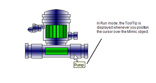
Use the ToolTip field to define the text that is shown on the ToolTip for the selected Mimic object. Simply enter the required text in the ToolTip field.
- Polyline—Use the following settings to define the pick action settings for polylines:
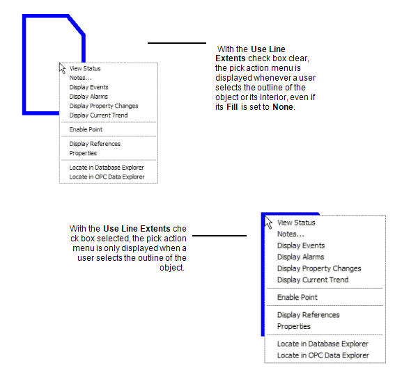
- Use Line Extents—Use this setting to control when a pick action menu is displayed for the object:
- If you select the Use Line Extents check box, any pick action menu that you associate with the object will only be displayed when a user selects the outline of the object. The pick action menu will not be displayed when a user selects another part of the object, such as the inside of a rectangle.
- If you clear the Use Line Extents check box, the pick action menu will be displayed when a user selects the outline or the inner part of the object.
The Use Line Extents feature is particularly useful with pipes and shapes that have no fill.
- Rotation—You can use the Rotation settings to define the pivot point of the object and the angle of rotation. This is useful for testing the rotation of an object before setting up a rotation animation. For example, if you are unsure about the exact angle which the object needs to be rotated by, you can experiment with the Rotation settings before making a decision. Once you know the correct angle, you can define it in an Animation (see Animations).
You can use these settings to examine the effects of a rotation:
- Pivot—Use the Pivot combo box to choose the anchor point for the rotation. The object will rotate from the selected side, corner, or center.
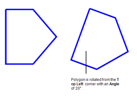
- Angle—Use the Angle field to enter the angle of rotation. You can enter positive or negative values.
When you have set the Pivot and Angle, close the Properties window and then switch the Mimic from Design mode into Run mode. The rotation only takes effect when the Mimic is displayed in Run mode.
- Pivot—Use the Pivot combo box to choose the anchor point for the rotation. The object will rotate from the selected side, corner, or center.
- Dynamic Sizing—You can use the Dynamic Sizing settings to define the type of resizing that will be applied to an object and the minimum size, maximum size, and current size of an object. This is useful for experimenting with sizes before using Animations to associate the size of an object with values in the database (see Animations).

You can use these settings to view the effects of a size alteration:
- Direction—Use the Direction combo boxes to select the direction of resizing, for example, you can set an animated rectangle to have its fill start from the center and increase to the edges when a point’s value increases.
There are two Direction combo boxes, one for horizontal directions and one for vertical. The options that are available are: Left to Right, Right to Left, Center Horizontal (start from the center expanding left and right), Top to Bottom, Bottom to Top, Center Vertical (start from the center expanding up and down).
- Min—Use the Min field to define the value that corresponds to the object's smallest size. Simply enter the required amount.
- Max—Use the Max field to define the value that corresponds to the object's largest size. Enter the required amount.
- Value—Use the Value field to define the object's current value. This sets the object to be a specific size in relation to the Min and Max limits you have defined. For example, if you enter a Value of 50 and the Min is 0 and the Max is 100, the object will be half of its maximum size (50 is midway in the range 0-100).
Enter the required amount.
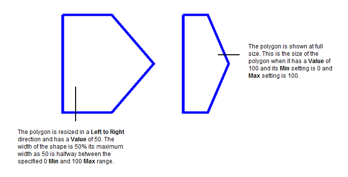
- Direction—Use the Direction combo boxes to select the direction of resizing, for example, you can set an animated rectangle to have its fill start from the center and increase to the edges when a point’s value increases.
- Dynamic Position—You can use the Dynamic Position settings to define the positioning of an object. This is useful for experimenting with positioning before using Animations to associate the position of an object with values in the database (see Animations).
Positioning animations set an object to move along a defined path. The position of the object on the path varies according to values in the database. For example, a Mimic object could move between the top corners of a Mimic depending on the value of a point.
To see the effect of dynamic positioning, you need to define these settings:
- Anchor—The Anchor setting allows you to specify which part of the Mimic object will be anchored to the path line. The 'anchored' part of the object stays in contact with the path line. For example, if the Anchor is set to Top, the object will move along the path line—the top of the object will remain on the pathline with the rest of the object being positioned underneath.
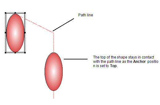
- Min—Use the Min field to define the value that corresponds to the start of the path line. Simply enter the required amount.
- Max—Use the Max field to define the value that corresponds to the end of the path line. Enter the required amount.
- Value—Use the Value field to define the object's current value. This sets the object to be at a specific location on the path line. The current position of the object is defined by its Value and is in relation to the Min and Max limits you have defined. For example, if you enter a Value of 50 and the Min is 0 and the Max is 100, the object will be half way along the path line (50 is midway in the range 0-100).
Enter the required amount.
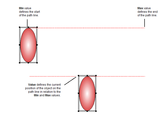
- Anchor—The Anchor setting allows you to specify which part of the Mimic object will be anchored to the path line. The 'anchored' part of the object stays in contact with the path line. For example, if the Anchor is set to Top, the object will move along the path line—the top of the object will remain on the pathline with the rest of the object being positioned underneath.
- Use Line Extents—Use this setting to control when a pick action menu is displayed for the object: