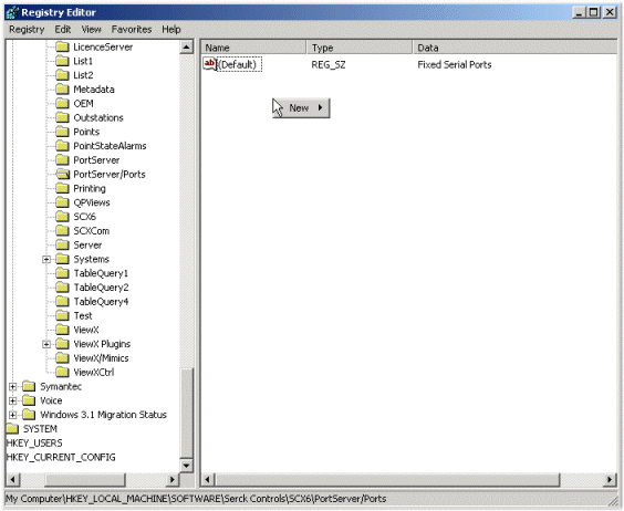
For remote serial communications via statically assigned ports (see Port Server on Remote Computer for Remote Access to Serial Ports), you need to reserve a port for use rather than allow the ports to be used on demand. To do this, you need to edit the registry settings on the remote computer.
To configure a serial port:
- On the remote computer, run regedit. (For more information, refer to your Microsoft Windows documentation).
- Expand the HKEY_LOCAL_MACHINE key to reveal its contents.
- Expand the SOFTWARE key to reveal its contents.
- Expand the Schneider Electric key to reveal its contents.
- Expand the Geo SCADA Expert key to reveal its contents.
- Expand the PortServer/Ports key to reveal its contents.
- Right-click in the right-hand pane that contains the contents of the Ports key.
A context sensitive menu is displayed. -

- Select the New option.
A further menu is displayed. - Select the String Value option.
A new string value is added. It is selected automatically, ready for you to enter its name. - Enter the TCP/IP port number that is to be used for the statically assigned port. We recommend that you use high numbers (over 10000) as these are less likely to already be in use by other applications.
If you specify a port that is already in use, the Geo SCADA Expert server will not be able to assign to the required port (see Troubleshooting Statically Assigned Ports).
- Press the Enter key or select another part of the interface to confirm the name entry.
- Right-click on the string value (the number string).
A context sensitive menu is displayed. - Select the Modify option.
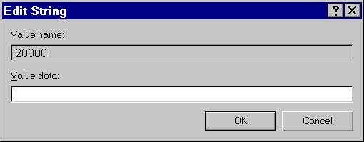
The Edit String window is displayed.
- In the Value Data field, enter the settings for the serial port that is to be used. The settings that you enter need to match the settings of the equipment attached to the port (the required settings should be provided in the documentation supplied by the equipment manufacturer).
Enter the settings (in comma separated value format):
- Port Name—The name of the serial port, for example, COM1.
- Baud Rate—The speed of data transfer via the port, for example, 9600.
- Number of Data Bits—The number of data bits used to transmit each byte of data. This is a number between 4 and 8 (inclusive), for example, 8.
- Parity—The setting for the parity bit that can be used as a method of error checking. The parity can be:
- N—For no parity
- E—Even parity.
- O—Odd parity.
- M—Mark parity.
- S—Space parity.
- Number of Stop Bits—Defines the number of bits that are placed after each character in the transmitted data. This is either 1, 1.5, or 2.
- Flow Control—Defines when and how data is transmitted. The flow control can be:
- NONE—Flow control is not applied to the data.
- XON XOFF—The operating system controls the flow of data by sending XON and XOFF signals to indicate whether the communications equipment can receive data.
- HARDWARE—The communications equipment uses Request to Send (RTS) and Clear to Send (CTS) signals to control the flow of data (and the operating system should stop data overruns from occurring).
- TOGGLE—Microsoft Windows controls the flow of data by sending a Request to Send (RTS) signal to the receiver when the transmission buffer contains data.
There is also an optional modem command suffix that can be used to activate modem sharing or RAS on a port. This modem command follows the Flow Control and is preceded by a semi-colon instead of a comma. For information on an appropriate modem command, please refer to the documentation supplied with your modem hardware.
Example:
COM3,9600,7,E,2,NONE
The port name is COM3, the Baud Rate is 9600, the number of Data Bits is 7, the Parity is even, the number of Stop Bits is 2, and Flow Control is not applied.
COM4,115200,8,N,1,HARDWARE;AT&F0E0V1S0=1
The port name is COM4, the Baud Rate is 115200, the number of Data Bits is 8, the Parity is Null, the number of Stop Bits is 2, the Flow Control is HARDWARE, and the modem command is AT&F0E0V1S0=1. The values are separated by commas except the Flow Control and Modem command which are separated by a semi-colon.
- Select the OK button.
The Edit String window is closed. - Repeat steps 7-15 inclusive for each additional serial port.
When you have configured the port(s), you need to Restart the Port Server Service.