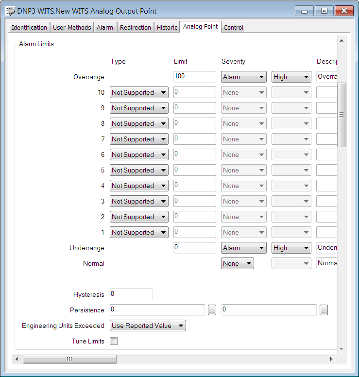
WITS analog points can have up to ten limits that you can configure to suit your requirements. The Device Profile defines how many limits a field device supports and also what types of limits are supported (see Display a WITS Device Profile).
Use the fields within the Alarm Limits section of the Analog Point tab to specify the properties for these alarm limits:

The upper part of the Alarm Limits section has a row of fields for each alarm limit. The number of rows you can use is defined by the Device Profile for your field device. The point Form shows the maximum number of available rows.
WITS specifies that the list of alarm limits is hierarchical, so the highest limit number has to have the highest limit value. For example, limit 5 has to have a higher limit value than limit 4, limit 4 has to have a higher limit value than limit 3 and so on. You also have to use the limits consecutively. For example, if your field device supports 3 limits, you use limits 1, 2 and 3.
The Normal state defines the usual operating range for the plant. This range will typically be between the lowest High value and the highest Low value.
Some types of analog point also have rows for the range limits Overrange, which is the maximum permitted value, and Underrange, which is the minimum permitted value.
Each limit is 1 incremental configuration record, and Overrange and Underrange share 1 incremental configuration record.
The following Alarm Limits properties are WITS specific:
-
Type—You can choose from High, Low or Disabled (High and Low are only available if supported by your field device).
High limits are for when then the point value increases away from the Normal range.
Low limits are for when the value decreases away from the Normal range.
Select Disabled for any limits that you do not want to use, even though they are available for your field device.
The Type is 'grayed out' and set to Not Supported for limits that are unavailable on your field device.
-
Severity—Use the left-hand Severity combo box to specify:
- What happens in Geo SCADA Expert when the point's value crosses a limit threshold (see Procedure for Configuring an Analog Point's Limits).
- What action the WITS field device takes when the point's value crosses a limit threshold (see Severity Types and Actions for WITS Database Points).
The left-hand Severity setting has a dual purpose for WITS, because your choice of setting applies to both Geo SCADA Expert and the field device.
Use the right-hand Severity combo box to specify the priority of events and alarms for the limit (in relation to other events and alarms on your system). For more details, see Defining Severities.
-
Hysteresis—Use this property to define the Hysteresis for a point limit or for all point limits (if supported by your field device).
The Hysteresis is an amount by which a point's value has to change before an alarm (for crossing a limit) is cleared. The point's value has to increase above a low limit or decrease below a high limit by the hysteresis amount. For more details, see Hysteresis for WITS Analog Points.
-
Persistence—Use this property to define Persistence for a point limit or for all point limits (if supported by your field device).
When Persistence is used, any change of point state is not reported unless the point remains in the new state for a specified amount of time (the Persistence Duration). Only then is the new state recorded. For more details, see Persistence for WITS Database Points.
The persistence is an amount of time, and you should only enter a time that is supported by your field device (see Display a WITS Device Profile).
- Engineering Units Exceeded—Use this property to define how Geo SCADA Expert processes Overrange and Underrange values. For more details, see Define how Overrange and Underrange Values are Processed.
The other Alarm Limits fields are common to many drivers (see Procedure for Configuring an Analog Point's Limits and see Define whether an Analog Point's Limits can be Tuned.
The availability of some of these settings, such as Hysteresis or Persistence, is dependent on your field device supporting that feature. For more details, see WITS Device Profiles.