AGA-9 USM Pulse Properties
The properties described in this topic are supported by Realflo version 7.02.1 onwards.
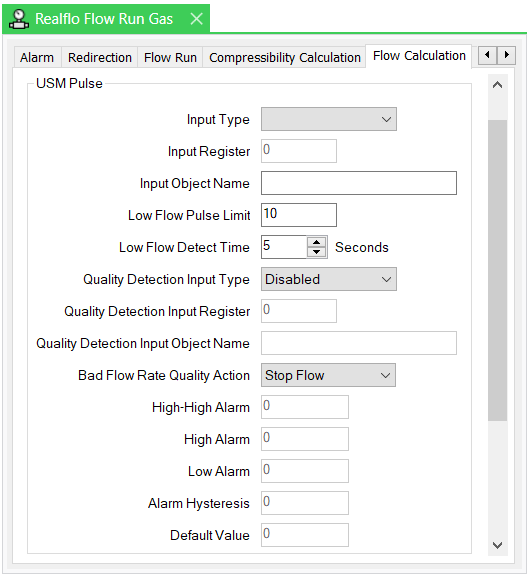
The USM Pulse section of the Flow Calculation tab is displayed if the selected Flow Calculation Type is AGA-9.
You can configure these properties directly in Geo SCADA Expert, or read the configuration into the Geo SCADA Expert database (see Configure or Read the Flow Run Configuration).
-
Input Type—Select the required input type. The options vary, depending on the type of Realflo controller on which the Flow Run is located. The options are as follows if the Flow Run is located on a SCADAPack x70 controller; this is indicated by the controller's Firmware Type being set to x70:
-
Database Object
If the Flow Run is located on another type of Realflo controller, the options are:
-
Telepace Long
-
ISaGRAF Integer.
The fields in the rest of this section vary, depending on the Input Type.
-
-
Input Register—Define the address of the register in the Flow Computer I/O database that contains the reading from the USM Pulse sensor. The valid register ranges are 30001 to 39998 and 40001 to 49998 inclusive.
The property is only available when the Input Type is set to an option other than Database Object.
-
Input Object Name—Define the name of the input object that is used for the USM pulse input. This property is only available when the Input Type is set to Database Object.
Ensure that the name that is specified in this field exactly matches that of the relevant object that exists in the Realflo controller. The name can be a maximum of 32 characters long. It has to start with a letter or underscore character (_) and can only contain alphanumeric characters and underscores (_). It cannot contain consecutive underscore characters and is not case sensitive.
-
Low Flow Pulse Limit—Specify the low flow pulse limit for the pulse input.
-
Low Flow Detect Time—Define the low flow detect time for the pulse input.
-
Quality Detection Input Type—Use to specify the type of input that is used for flow rate quality detection. Select the required input type. The options vary, depending on the type of Realflo controller on which the Flow Run is located. The options are as follows if the Flow Run is located on a SCADAPack x70 controller; this is indicated by the controller's Firmware Type being set to x70:
-
Disabled—This is the default option
-
Database Object.
If the Flow Run is located on another type of Realflo controller, the options are:
-
Disabled—This is the default option
-
Input Register.
-
-
Quality Detection Input Register—Define the address of the register in the Flow Computer I/O database that contains the reading from the flow rate quality detection sensor. The valid register ranges are 1 to 3890 and 10001 to 14096 inclusive.
The property is only available when the Quality Detection Input Type is set to Input Register.
-
Quality Detection Input Object Name—Define the name of the input object that is used for the flow rate quality detection. This property is only available when the Quality Detection Input Type is set to Database Object.
Ensure that the name that is specified in this field exactly matches that of the relevant object that exists in the Realflo controller. The name can be a maximum of 32 characters long. It has to start with a letter or underscore character (_) and can only contain alphanumeric characters and underscores (_). It cannot contain consecutive underscore characters and is not case sensitive.
-
Bad Flow Rate Quality Action—Use to define the bad flow rate quality action for the USM pulse input. Choose from:
-
Stop Flow
-
Accumulate Flow
-
The input alarms section of the USM Pulse section enables you to set the alarm thresholds for alarm types that have been enabled in the Inputs section of the Flow Run tab.
Use the following properties to configure the alarm limits and alarm-related properties in the USM Pulse section:
-
High-High Alarm—Set the high-high alarm threshold for the USM pulse value. A valid entry is any value within the USM pulse scale range that is higher than or equal to the value of the High Alarm threshold. The default is the USM pulse at Full Scale for analog inputs, or the Upper Operating Limit for sensors. This control is enabled if the High-High Alarm option is enabled in the Inputs section, otherwise this control is unavailable.
-
High Alarm—Set the high alarm threshold for the USM pulse value. A valid entry is any value within the USM pulse scale range that is higher than the value of the Low Alarm threshold, and is lower than or equal to the value of the High-High Alarm threshold. The default is the USM pulse at Full Scale for analog inputs, or the Upper Operating Limit for sensors. This control is enabled if the High Alarm option is enabled in the Inputs section, otherwise this control is unavailable.
-
Low Alarm—Set the low alarm threshold for the USM pulse value. A valid entry is any value within the USM pulse scale range that is lower than the value of the High Alarm threshold. The default is the USM pulse at Full Scale for analog inputs, or the Upper Operating Limit for sensors. This control is enabled if the Low Alarm option is enabled in the Inputs section, otherwise this control is unavailable.
-
Alarm Hysteresis—Set the hysteresis value for each configured alarm type. The hysteresis setting determines at what level alarms are cleared when the input variable reading returns to a non-alarm state. This setting reduces nuisance alarms around the alarm limit.
-
Default Value—Set the value for the input variable to use when alarms are enabled and the Values in Alarm option in the Inputs section is set to Use Default Values.
Further Information
For more detailed information on these properties, see the documentation provided with the Realflo application.