The Meter Input tab fields vary depending on the Meter Input Type that you select. This sections describes the fields related to either the Mass (Pulse) or Volume (Pulse) Meter Input Type. (The latter type of meter input only applies to Liquid and Water Flow Runs.)
You can configure these properties directly in Geo SCADA Expert, or read the configuration into the Geo SCADA Expert database (see Configure or Read the Flow Run Configuration).
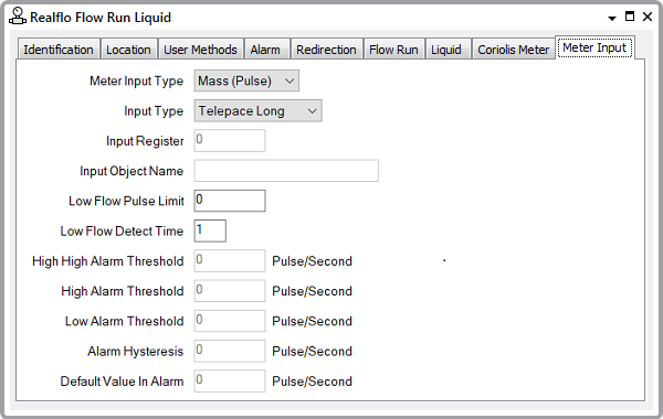
- Input Type—This section describes the options that are available when the Meter Input Type is set to Mass (Pulse) or Volume (Pulse). Select the required input type. The options vary, depending on the type of Realflo controller on which the Flow Run is located. The options are as follows if the Flow Run is located on a SCADAPack x70 controller; this is indicated by the controller's Firmware Type being set to x70:
- Database Object.
If the Flow Run is located on another type of Realflo controller, the options are:
- Telepace Long
- ISaGRAF integer.
The fields in the rest of this section vary, depending on the Input Type.
-
Input Register—Define the address of the register that contains the input value. Valid register values are in the following ranges 30001 to 39998 and 40001 to 49998.
This field is unavailable for use when the Input Type is set to Database Object.
- Input Object Name—This Input Object Name field applies instead of the Input Register field when the Input Type is set to Database Object. Use to specify the name of the meter input object in the Flow Computer I/O database.
Ensure that the name that is specified in this field exactly matches that of the relevant object that exists in the Realflo controller. The name can be a maximum of 32 characters long. It has to start with a letter or underscore character (_) and can only contain alphanumeric characters and underscores (_). It cannot contain consecutive underscore characters and is not case sensitive.
- Low Flow Pulse Limit—Set the number of pulses below which a low flow alarm will occur. When the number of pulses falls below the Low Flow Pulse Limit, pulses are not accumulated against volume or rate until the number of pulses rises above the low flow pulse limit again. Setting the low flow pulse limit to 0, disables low flow detect. The default value is 10.
- Low Flow Detect Time—Set the length of time the number of pulses needs to remain below the Low Flow Pulse Limit for a low flow alarm to occur. Valid values are from 1 to 60 seconds. The default value is 5.
The input alarms fields allow you to set the alarm thresholds for alarm types that have been enabled in the Inputs section on the Flow Run tab.
Use the following to configure alarm limits:
- High-High Alarm Threshold—Set the high-high alarm threshold for the pulse rate. A valid entry is any value within the pulse rate range that is higher than or equal to the value of the High Alarm Threshold. This control is enabled if the High-High Alarm option is enabled in the Inputs section.
- High Alarm Threshold—Set a high alarm threshold for the pulse rate. A valid entry is any value within the pulse rate range that is higher than the value of the Low Alarm Threshold, and is lower than or equal to the value of the High-High Alarm Threshold. This control is enabled if the High Alarm option is enabled in the Inputs section.
- Low Alarm Threshold—This allows you to set a low alarm threshold for the rate. A valid entry is any value in the pulse rate range that is lower than the value of the High Alarm Threshold. This control is enabled if the Low Alarm option is enabled in the Inputs section.
- Alarm Hysteresis—Set the hysteresis value for each configured alarm type. The hysteresis setting determines at what level alarms are cleared when the input variable reading returns to a non-alarm state. This setting reduces nuisance alarms around the alarm threshold. Enter a value in the full-scale range of the input variable.
Further Information
For more detailed information on these properties, see the documentation provided with the Realflo application.