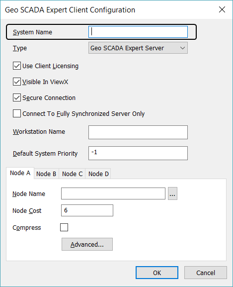
When you add or edit a system connection, you use the Client Configuration window to configure the Virtual ViewX system settings. The following are the main settings that are required to enable the Virtual ViewX server to connect to a Geo SCADA Expert server. For more complex configuration you can access the Advanced section.
For properties not mentioned in this guide, see Edit an Existing ViewX Client - System Connection in the Geo SCADA Expert Guide to Client Configuration.
Do not specify a Workstation Name on a Virtual ViewX server. If a Workstation Name is specified, all Virtual ViewX clients that attempt to connect to the Virtual ViewX server will be assigned the same Workstation Name. As a Workstation Name has to be unique per system, attempts made by other clients to connect using the same Workstation Name as a client that is already connected will be rejected. As such, Workstation Names only apply to ViewX clients (as opposed to Virtual ViewX clients).
You use the Client Configuration window to add an entry for each Geo SCADA Expert system to which the Virtual ViewX server is to connect. The System Name that you allocate for each system connection is the name that will be used to label the system within Virtual ViewX; it does not rename the system at the server.
To define the system name and type for a system on a Virtual ViewX server:
- Display the Client Configuration Window for the connection that you want to add or edit.
- Enter the name of the system in the System Name field. The name that you enter will be shown as the name of the system in Virtual ViewX clients that connect to the Virtual ViewX server.

You will be required to restart the IIS manager to implement a new server connection or any changes to an existing server connection.
Refer to Microsoft® documentation for information on how to restart the IIS manager or contact the System Administrator.
A Virtual ViewX server can connect to a maximum of 4 servers in a single system. The number of servers to which a server needs to connect varies according to the architecture of the system, for example, a Hot-Standby system has 2 servers (Main and Standby) whereas a Triple Standby system with a Permanent Standby has 4 (the Main, Standby 1, Standby 2, and the Permanent Standby).
To define the node settings for a system connection:
- Select the tab for the Node that you want to configure. We recommend that you use the Node tabs in order, for example, if you need to define 2 Nodes, use the Node A and Node B tab and ignore the Node C and Node D tab.

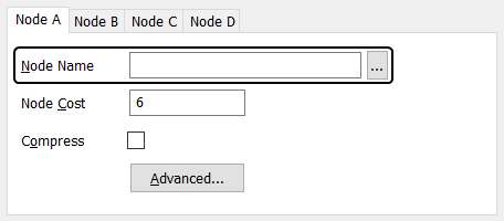
- Define the Node Name setting. You have to define the node name or IP address of the node (the server to which the Virtual ViewX Server will connect). If you leave the Node Name setting blank, the system will use the IP Address of the computer on which you are configuring the Virtual ViewX server as the Node Name setting.
Enter the name or IP address of the server node:
Either:
- Use the browse button next to the Node Name field to display a browse window. Use the browse window to select the computer (node) that is the server, then select the OK button to confirm the selection.
Or:
- In the Node Name field, type the name of the server or the server's IP address.
ATTENTION: For dual Ethernet arrangements, you have to enter the IP addresses for the nodes.
- Use the browse button next to the Node Name field to display a browse window. Use the browse window to select the computer (node) that is the server, then select the OK button to confirm the selection.
You use the Node settings on the Client Configuration window to define which Geo SCADA Expert servers the Virtual ViewX server can connect to via the System connection. There is a Node tab for each Geo SCADA Expert server.
The Node tabs should be used as follows:
Lone Server
Use the Node A tab to define the connection between the Virtual ViewX server and the Geo SCADA Expert server.
Hot-Standby Pair
Use the Node A tab to define the connection between the Virtual ViewX server and the first Geo SCADA Expert server, and the Node B tab to define the connection between the Virtual ViewX server and the second Geo SCADA Expert server.
Hot-Standby Pair with 1 Permanent Standby
Use the Node A tab to define the connection between the Virtual ViewX server and the first Geo SCADA Expert server, and the Node B tab to define the connection between the Virtual ViewX server and the second Geo SCADA Expert server. Use the Node C tab to define the connection between the Virtual ViewX server and the permanent standby server.
Hot-Standby Pair with 2 Permanent Standbys
Use the Node A tab to define the connection between the Virtual ViewX server and the first Geo SCADA Expert server, and the Node B tab to define the connection between the Virtual ViewX server and the second Geo SCADA Expert server. Use the Node C tab to define the connection between the Virtual ViewX server and the first permanent standby server, and the Node D tab to define the connection between the Virtual ViewX server and the second permanent standby server.
Hot-Standby Pair (Dual Ethernet)
Use the Node A and Node B tabs to define the connections between the client and one server (each Node tab defines the settings for a network card), and use the Node C and Node D tabs to define the connections between the Virtual ViewX server and the alternate Geo SCADA Expert server.
For Dual Ethernet arrangements, you have to define the Node Name as an IP address so that the client can differentiate between the network cards.
Triple Standby
Use the Node A tab to define the connection between the Virtual ViewX server and the first Geo SCADA Expert server. Use the Node B and Node C tabs to define the connections between the Virtual ViewX server and the second and third Geo SCADA Expert servers.
Triple Standby with Permanent Standby
Use the Node A tab to define the connection between the Virtual ViewX server and the first Geo SCADA Expert server. Use the Node B and Node C tabs to define the connections between the Virtual ViewX server and the second and third Geo SCADA Expert servers. For the Permanent Standby server, use the Node D tab.
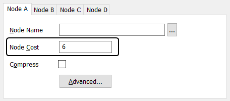
Each connection is allocated a cost number that is used by the system to determine the order of preference for the connections—the connection with the lowest cost is the preferred connection. Usually, the cost indicates the efficiency of the connection, with the more efficient connections having the lowest cost numbers.
To define the node cost settings for a system connection:
- Select the tab for the Node that you want to configure.
- Use the Node Cost field to define the cost. The cost is used to define the relative efficiency of each connection. You can enter any number, but remember that the number will be used as part of range and will be compared to the Node Cost numbers of any other connections

- Select the OK button to confirm your selections and close the Client Configuration window.
When a Virtual ViewX server connects to a server, it automatically connects to the server that has the lowest Node Cost value and is available. This sets the Virtual ViewX server to use the most suitable route to the system. If there are two connections that have the same Node Cost, the Virtual ViewX server will connect to the server that is Main.
To define the Node Cost for a connection, you need to have an appreciation of the type and efficiency of each connection:
- If the connections are via a Local Area Network (LAN), you should set the Node Cost of each connection to the same amount. This means that a Virtual ViewX server only connects to the Main server.
- If there are Wide Area Network (WAN) connections, you should set the Node Cost to indicate the amount of bandwidth that is available for the connection. The connections that provide the lowest amount of bandwidth are the least efficient and so should have the highest Node Cost values.
You can use any numbers to define the Node Costs, but the lowest number in your chosen range must be allocated to the connection that provides the most suitable route to the server. You can allocate subsequent numbers to the next most efficient connection (the least efficient connection will have the highest number in the range).
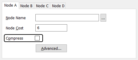
You can use the Compress check box on the Client Configuration window to enable and disable data compression for the Virtual ViewX server - system connection.
To enable or disable the compression feature for a node:
- Select the Compress check box to enable the compression feature or clear it to disable the feature.

- Select the OK button to confirm your choice.
The advantage of having compression enabled is that it reduces the amount of data that has to be sent, and so the data can be transferred more quickly. However, compression makes greater use of the processor and so there is an overhead on both the Geo SCADA Expert server and Virtual ViewX server. For this reason, compression is usually only enabled on systems that are connected via slow networks (low bandwidth, typically less than 10Mb per second).
When using the Compress feature, you need to consider which servers in your system architecture are needed to compress and decompress the data (each server in your system has a Compress feature).
You can quantify the effects of the compression feature by examining the Server>Server Links statistics on the Server Status Tool (see Server Links).