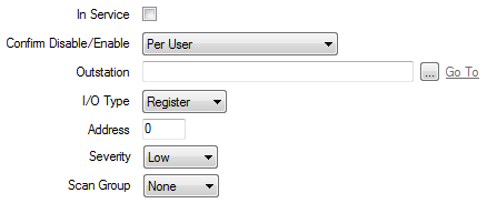
Use the fields at the top of the <Point Type> tab to configure the common point properties.
The following fields are common to the points on Kingfisher outstations. For fields that are not described here, see the relevant point configuration section.

Use to specify whether the point is active or inactive (see Placing an Item In Service in the Geo SCADA Expert Guide to Core Configuration).
Users with the required permissions can disable a point that is In Service, or enable a point that is not In Service. Such actions are carried out using the Disable Point and Enable Point pick actions.
Use the Confirm Disable/Enable combo box to specify whether a confirmation dialog box is displayed whenever an operator requests that this point is disabled or enabled (see Requesting Confirmation of Action Requests in the Geo SCADA Expert Guide to Core Configuration).
Use to specify the outstation on which a point is located. Use the browse button to display a Reference browse window and select the relevant outstation from the window.
Points on a Kingfisher outstation can be physical or internal points. Use the I/O Type combo box to specify the point type. Choose from:
- Register—The point is an internal point that exists in the outstation software.
- Hardware—The point is a physical point for which I/O hardware connections exist.
On some systems, Geo SCADA Expert communicates with Kingfisher outstations using a Master/Remote setup (see Typical Master/Remote Scenarios). With this type of arrangement, each Kingfisher Remote outstation monitors the change of state of its inputs and uses Kingfisher RTUTX statements to send the information to the Kingfisher Master outstation. The information then appears in the Master outstation’s network address registers. It is this register information that is read by Geo SCADA Expert. (Geo SCADA Expert reads the information from the local Master outstation only and not from the Remote outstations on the network.)
Use to specify the point’s address.
For Register points, specify the point’s register address, in the range 1 to 2048.
For Hardware points, specify the slot number, in the range 1 to 64.
Use this combo box to define the severity of any non-state events or alarms for the point. For more information on severities, see Defining Severities.
This field is only displayed if the Area of Interest feature is enabled on your system. Use the field to specify the Area of Interest with which any non-state related point alarms or events are to be associated (see Assign a Different Area of Interest to an Item’s Alarms and Events).
Use the combo box to specify the Scan Group with which the point is associated. The Scan Group determines the frequency with which the driver updates the server with the current value for the point.
Specify the frequency of the group on the Scan Parameters tab of the associated Channel Form (see Define Intervals for Timed Current Data Updates).