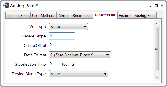
You use the Device Point tab to configure the following SCADAPack 50 device properties:

- Var Type—Select a combo box option to specify the type of the device logical point (for example, 0-20mA, Counter, Digital Input or Modbus Sensor).
NOTICE
LOSS OF DATA
When you set the Var Type, avoid causing a mismatch between the device's point configuration and the Geo SCADA Expert point configuration. A mismatch could result in a loss of data.Failure to follow these instructions could result in a loss of data. - Device Slope—Enter the multiplier that the device should apply to a raw logged value, to scale it before it sends the value to Geo SCADA Expert.
Example:
A sensor might report raw values between 0 and 1. If the sensor is a 600 bar pressure sensor, you might enter a slope of 600. The device would then multiply the raw values by 600 to convert them into bars.
- Device Offset—Enter a lag offset value. This is a constant value that the device adds to a logged raw value (for example, to correct sensor anomalies) before it sends the value to Geo SCADA Expert.
- Data Format—Specify the precision (the number of decimal places) with which the device should report a point's values to Geo SCADA Expert. Select a combo box option. The default precision is defined by the point's Var Type.
- Stabilization Time—Specify the length of time (in 100 millisecond units) between the time when the device awakes and when it records a point value. The longer the Stabilization Time, the greater will be the device's power consumption.
- Device Alarm Type—Specify the value thresholds that control when the device should send alarm messages to Geo SCADA Expert. The thresholds that you specify are engineering values. Geo SCADA Expert may scale these values before sending them to the device (see Configure Point Scaling) and (see Alarm Limits). Select a combo box option.
For Analog Points, the options are: None, Minimums (Low, LowLow), Maximums (High, HighHigh), MinMax (Low, High), MinMax (LowLow, HighHigh). For more information about setting alarm thresholds for an analog point, see Alarm Limits.
For Digital Points, the options are: None, Min - State 0, Max - State 1. For more information about setting the states for a digital point, see Point State Properties.
For Counter Points, the options are None and Maximums (High, HighHigh). For more information about setting the alarm thresholds for a counter point, see Alarm Limits.
Example:
A sensor that is associated with a device analog point might report values in the range 1 to 100. You might set alarm thresholds as follows: Low Low=5, Low=20, High=80, High High=95. If you then select a Device Alarm Type of MinMax (Low, High), the device would send alarm messages when a value falls below 20 (Low) or when it rises above 80 (High).