Configure the Properties on the Mapping Tab
The Forms of SCADAPack x70 Analog, Digital, and Counter Configuration items include a Mapping tab. By default, the settings on this tab are disabled (the Mapping property is set to 'No Mapping').
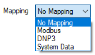
You only need to set the 'Mapping' property to another option if one of the following applies:
Either:
- The SCADAPack x70 device with which the SCADAPack x70 Configuration item is associated requests data from a Slave device
and:
- The SCADAPack x70 Configuration item that you are configuring represents an input or output on that Slave device.
If both of the above apply, use the Mapping property to specify the communications protocol that the SCADAPack x70 device is to use to communicate with the Slave device. Other properties will become available on the Mapping tab; use the properties to specify the required settings to enable the SCADAPack x70 device to retrieve the data from the Slave device.
If you want to use the data from the Slave device in Geo SCADA Expert, in addition to configuring the relevant settings on the Mapping tab, you need to associate the SCADAPack x70 Configuration item with a SCADAPack x70 protocol-specific Point. You use the Point to specify how Geo SCADA Expert processes the data that it retrieves from the Slave device for that particular input or output (see Points and Configuration Items Supported by the Driver).
Or:
- The SCADAPack x70 Analog or Digital Configuration item is being used to monitor or control system data on a SCADAPack x70 device.
In which case, use the Mapping property to specify the item of system data with which the SCADAPack x70 Configuration item is associated.
If you want to use the SCADAPack x70 device's system data in Geo SCADA Expert, in addition to configuring the relevant settings on the Mapping tab, you need to associate the SCADAPack x70 Configuration item with a SCADAPack x70 protocol-specific Point. You use the Point to specify how Geo SCADA Expert processes the system data that it retrieves from the SCADAPack x70 device for that particular input or output (see Points and Configuration Items Supported by the Driver).
You only need to set the Mapping property to 'Modbus' if either of the following apply:
- The SCADAPack x70 device with which this Analog, Digital, or Counter Configuration item is associated is operating as a Modbus RTU Master. Additionally, the input or output that this Analog, Digital, or Counter Configuration item represents is on a Modbus Slave Device from which the SCADAPack x70 device requests data.
- The SCADAPack x70 device with which this Analog, Digital, or Counter Configuration item is associated is operating as a Modbus/TCP Client. Additionally, the input or output that this Analog, Digital, or Counter Configuration item represents is on a Modbus /TCP Server from which the SCADAPack x70 device requests data.
With either of the above scenarios, you need to set the Mapping property to ‘Modbus’, whereupon the following properties are displayed. Configure the properties as required:
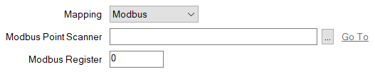
- Modbus Point Scanner—Specify the SCADAPack x70 Modbus Point Scanner item that is being used to map to the point on the Modbus RTU Slave or Modbus/TCP Server. Use the browse button to display a Reference browse window and then select the required entry from the window.
- Modbus Register—Specify the Modbus Register address at which the point is located in the Modbus RTU Slave or Modbus/TCP Server. The address has to be within the range that is available to the SCADAPack x70 Modbus Point Scanner item specified in the field above.
You only need to set the Mapping property to ‘DNP3’ if the following applies:
- The SCADAPack x70 device with which this Analog, Digital, or Counter Configuration item is associated is operating as a DNP3 Master. Additionally, the input or output that the Analog, Digital, or Counter Configuration item represents is on a DNP3 Slave from which the SCADAPack x70 device requests events. (A DNP3 Slave can be another SCADAPack x70 device, or a different type of device, such as a remote terminal unit (RTU), a programmable logic controller (PLC), or a smart device with DNP3 protocol capability.)
With the above scenario, you need to set the Mapping property to ‘DNP3’, whereupon the following properties are displayed. Configure the properties as required:
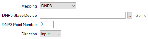
- DNP3 Slave Device—Specify the SCADAPack x70 DNP3 Slave Device item that is being used to map to the point on the DNP3 Slave. Use the browse button to display a Reference browse window and then select the required entry from the window.
- DNP3 Point Number—Specify the DNP3 Point Number that is assigned to the point on the DNP3 Slave.
- Direction—Use the combo box to specify whether the point on the Slave device is an Input or Output. With a Counter Configuration item, the direction is set to 'Input'.
You only need to set the Mapping property to 'System Data' on a SCADAPack x70 Analog or Digital Configuration item that is being used to monitor or control system data on a SCADAPack x70 device. When you do so, the following properties are displayed:
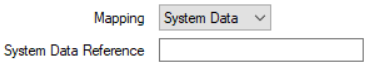
- System Data Reference—Enter the name of the item of system data that this particular Analog or Digital Configuration item is to reference in the SCADAPack x70 device. The entry should match the name of the item of system data exactly. Refer to the documentation provided with the SCADAPack x70 device for information about the items of system data that are supported by the device.
The entry must begin with the
SYS_prefix and can be a maximum of 32 characters long. It can contain a mixture of alphanumeric and underscore characters, but cannot contain any spaces.There is no automatic checking mechanism to confirm whether the entry in the System Data Reference field does match the name of an item of system data in the SCADAPack x70 device. As such, care should be taken to manually check that the string entered in the field is correct.
Further Information
Specify the role of a SCADAPack x70 device in a SCADA network: see Configure the Device Options.
Configure Geo SCADA Expert to Communicate with, and Monitor the Status of, Downstream Slave Devices.
Use system data to trigger Daylight Saving Time (DST) adjustments: see Configure the Time Zone Settings for Local Operations.