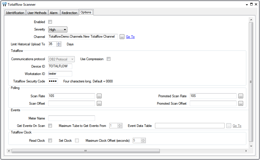
The Totalflow-specific configuration settings for the Totalflow Scanner object are on the Scanner Options tab. There are also additional configuration fields that do not appear on the configuration form, but do appear in the schema (Scanner Configuration Fields).
To configure a Totalflow Scanner display the Properties window for a Totalflow Scanner item and select the Options tab.

Complete the following fields:
- Enabled—Select this check box for the scanner to be in service.
- Severity—Use this combo box to set the alarm severity for the scanner.
- Channel—Select the browse button to display a Reference browse window. Use the window to locate and select the Totalflow Channel item with which the Scanner object is associated. The Scanner remains inactive until you connect it to a Channel.
- Limit Historical Upload—Use this field to restrict the number of days of historical data that the driver polls during historic data retrieval, including event table retrieval. The field limits historical data retrieval to this number of days in the past.
- Communications Protocol—This field indicates the communications protocol that the Scanner uses to communicate with the TotalFlow device. The currently supported protocol is the DB2 Protocol.
- Use Compression—Select this check box to compress the DB2 protocol messages that are exchanged with the Totalflow device. You might want to do this, for example, if communications is via a radio network that has a low bandwidth.
- Device ID—This value has to match the Device ID in the Totalflow device.
- Workstation ID—Specify an arbitrary value to identify the workstation (the value does not need to match a setting in the Totalflow device). The value is used by the protocol and the Totalflow device to determine which host is accessing the Totalflow device.
- Totalflow Security Code—This value has to match the security code in the Totalflow device.
- Scan Rate—Use this field to specify how often the scanner is to poll the Totalflow and update the points that reference this Totalflow Scanner.
- Scan Offset—Use this field to specify the offset to the scan rate. For example, if you enter ‘Hour’ in this field, the Totalflow Scanner will poll at the hour, and then at whatever rate is specified in the Scan Rate field.
- Promoted Scan Rate—Use this field to specify how often the scanner will poll the Totalflow and update the points that reference this Totalflow Scanner when promoted scanning is enabled. To enable promoted scanning, call the Enable Promoted Scanning method on the Totalflow Scanner.
- Promoted Scan Offset—Use this field to specify the offset to the promoted scan rate. For example, if you enter ‘Hour’ in this field, the Totalflow Scanner will poll at the hour, and then at whatever rate is specified in the Promoted Scan Rate field, when promoted scanning is enabled.
- Meter Name—This field is optional. Whatever text you enter here is populated in the ‘MeterName’ column of the Totalflow Event Data Table. Because the Event Data Table can hold data for more than one Totalflow, the Meter Name field provides a convenient way to filter events from different devices. If you are not getting events via this scanner, you can leave this field blank.
- Get Events on Scan—Select this check box if the Totalflow Scanner is to poll for new events on each scan. If this box is selected, ensure that the Event Data Table ID field is populated correctly (see below).
- Maximum Tube to Get Events From—Use this field to specify the highest tube number for which the scanner is to retrieve events. When a scan occurs, the scanner will build the DB2 request such that events for tubes higher than this value are not requested. The field only applies when the Get Events on Scan check box is selected (see above).
- Event Data Table—If the Get Events on Scan check box is selected, you need to populate this field with a reference to a Totalflow Event Data Table. For further information, Event Data Table.
- Read Clock — Select this check box for the Totalflow Scanner to read the clock in the Totalflow on each scan and put the time that is read in the TimeLocal data field. The driver also updates the ClockOffsetToHostSecs field, which contains the difference between the Totalflow clock and the Geo SCADA Expert clock.
- Set Clock— Select this check box for the Totalflow Scanner to read the clock in the Totalflow on each scan and put the time that is read in the TimeLocal data field. If the difference between the Totalflow clock and the host clock is greater than the number of seconds specified in the Maximum Clock Offset field (see below), then the driver will set the clock in the Totalflow to the time at the host.
- Maximum Clock Offset—This field only applies when the Set Clock check box is selected. Use the field to specify the maximum allowable difference between the host clock and the Totalflow clock in seconds. If the offset between the two clocks is greater than the number of seconds specified in this field when the driver scans the Totalflow device, the driver will set the time in the Totalflow to the host time.
Further Information