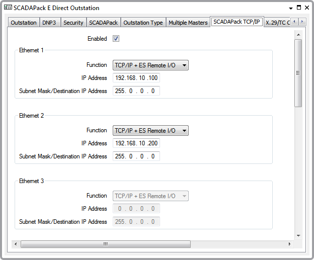
SCADAPack E outstations are supplied with 1, 2 or 3 Ethernet interfaces. Use the fields within the Ethernet 1 and, if applicable, the Ethernet 2 and Ethernet 3 sections of the SCADAPack TCP/IP tab to define the general properties for the interface(s).
If the outstation does not have the Ethernet 2 and Ethernet 3 interfaces, the fields within those sections of the tab are ‘grayed out’ and unavailable for use. This is defined by the Outstation Type property (see Specify the Outstation Type).

- Function—Use the combo box to define the function of each Ethernet interface. The options vary, depending on the Outstation Type, but will include a combination of the following:
- ES Remote I/O—Enables the Ethernet interface for ES Remote I/O only. The other fields in the Ethernet section are ‘grayed out’ and unavailable for use.
- TCP/IP + ES Remote I/O—Enables the Ethernet interface for both TCP/IP and ES Remote I/O. This is the default option.
- TCP/IP Disabled—The Ethernet interface is not used. The other fields in the Ethernet section are ‘grayed out’ and unavailable for use.
- TCP/IP Enabled—Enables the Ethernet interface for TCP/IP on a SCADAPack 350E or 357E outstation.
- IP Address—Use to specify an appropriate IP Address for the Ethernet interface.
If the SCADAPack E outstation is to communicate with a TCP/IP device that is not on either of its local Ethernet subnets, you will need to create an IP Route Table with a route entry for the destination device (see Add and Configure the Entries in an IP Route Table). You will need to link the IP Route Table to the outstation (see Specify IP Route and BOOTP Tables).
- Subnet Mask/Destination IP Address—Use to specify an appropriate Subnet Mask if the Ethernet interface is to be used for TCP/IP communications.