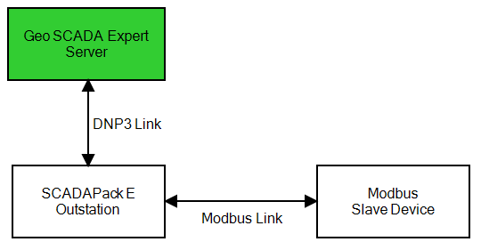
You can connect a Modbus slave device to a DNP3 SCADAPack E outstation.

Before you can do this, you need to set up and configure a DNP3 SCADAPack E outstation (see Configuring DNP3 SCADAPack E Outstations)).
The SCADAPack E outstation must be running firmware version 8.12 or higher.
For each Modbus slave device that you connect, you need to add and configure a Geo SCADA ExpertDNP3 SCADAPack E Modbus Slave Device database item (see Add an Item to the Database). This section describes this database item.
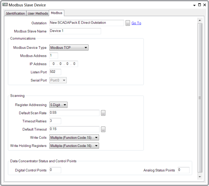
You configure the DNP3 SCADAPack E Modbus Slave Device item by setting properties on its configuration Form. The Form has several tabs.This section describes how to configure properties on the Modbus tab. The tab properties are described below:

- Outstation—Use to Specify the SCADAPack Outstation with Which the I/O is Associated.
- Modbus Slave Name—Specify the name of the Modbus slave device. The name needs to be unique for each SCADAPack E outstation and can be up to 32 characters in length. You can use alphanumeric characters, underscores and hyphens. You cannot use spaces.
In the Communications section of the Modbus tab, you specify the settings for the connection between the SCADAPack E outstation and the Modbus slave device.
- Modbus Device Type—Use this combo box to select the protocol used by the communication link between the SCADAPack E outstation and the Modbus slave device. Select from Modbus TCP (Transmission Control Protocol) and Modbus Serial RTU.
- Modbus Address—Specify the network address of the Modbus slave device. The address needs to be within the range 1 to 255.
- IP Address—This field is only available if you selected Modbus TCP for the Modbus Device Type. Specify the IP address of the Modbus slave device.
- Listen Port—This field is only available if you selected Modbus TCP for the Modbus Device Type. If the slave device can initiate a network connection, use this field to specify the TCP/IP port on which the SCADAPack E outstation should 'listen' for connection requests. The port number needs to be unique to the SCADAPack E outstation.
- Serial Port—This field is only available if you selected Modbus Serial RTU for the Modbus Device Type. Use this combo box to specify the serial port on the SCADAPack E outstation used by the outstation to communicate with the Modbus slave device. You need to ensure that the Function of this port is set to Modbus Master (Modbus RTU)(see Configure the Properties of the Individual Ports).
In the Scanning section of the Modbus tab, you can specify the settings that enable the SCADAPack E outstation to scan the Modbus slave device. Scanning is the process by which the SCADAPack E outstation reads the registers and coils on the slave device for any current data (a coil is a discreet single-bit register). The SCADAPack E outstation will retrieve and process any such data and then map it to DNP3 points. The data will not be stored in the Geo SCADA Expert database.
- Register Addressing—Use this combo box to specify whether the register addresses on the Modbus slave device have 5 digits or 6 digits.
- Default Scan Rate—Enter the frequency rate at which the SCADAPack E outstation should scan the Modbus slave device registers for point data. The default rate is 0.5 seconds. Specify the rate in the OPC Time Format. Enter the rate directly in the field (see Specify a Time Period in the OPC Time Format in the Geo SCADA Expert Guide to Core Configuration) or use the Interval Window to specify the rate that you require.
- Timeout Retries—Enter the number of times that the SCADAPack E outstation should attempt to scan the Modbus slave device before it determines that it cannot communicate with the device.
- Default Timeout—Enter the amount of time that the SCADAPack E outstation should wait for a response from the Modbus slave device. If the outstation does not get a response in this time, the outstation will try the scan again until it exceeds the Timeout Retries count. If the outstation still cannot get a response after the retries, it will determine that it cannot communicate with the device. Geo SCADA Expert sets the default time interval to 0.1 seconds. Specify the time interval in the OPC Time Format. Enter the interval directly in the field (see Specify a Time Period in the OPC Time Format in the Geo SCADA Expert Guide to Core Configuration) or use the Interval Window to specify the interval that you require. The timeout value that you enter is for each scan.
- Write Coils—Use this combo box to select the function codes that the SCADAPack E outstation should use to write to coils on the slave device. Select from the following:
- Multiple (Function Code 15)—Used to force each coil, in a sequence of coils, to be in an 'on' or 'off' state.
- Single (Function Code 5)—Used to force a single coil to be in an 'on' or 'off' state.
- Write Holding Registers—Use this combo box to select the function codes that the SCADAPack E outstation should use to write data to holding registers on the slave device. Select from the following:
- Multiple (Function Code 16)—Used to write data (2 bytes per register) to a block of contiguous holding registers (1 to 123 registers)
- Multiple (Function Code 6)—Used to write data (2 bytes) to a single holding register.
In the Data Concentrator Status and Control Points section of the Modbus tab, you can specify the points that:
- Enable users to control the outstation's scanning of the Modbus slave device. Users can control the scanning by setting the point values.
- Report the status of the slave device.
The settings are as follows:
- Digital Control Points—This is a block of 10 consecutive binary points that enable users to control activity related to the scanning of the Modbus slave device. Users can control the scanning by setting the point values. Enter the DNP3 address of the first point in the block of points. This will be the point number of the Service Control point. This point controls whether the SCADAPack outstation will scan the Modbus slave device. If you set the Service Control point to have a value of 1, the outstation will poll the device. If you set the point to have a value of 0, the outstation will not poll the device.
Each binary point in the block needs to have its Point Type set to User (Derived) in order to be a valid control point (see Configure Common Properties of DNP3 SCADAPack Points).
- Analog Status Points—The SCADAPack E outstation can report the status of the Modbus slave device. It uses a block of 10 consecutive analog points to do this. Enter the DNP3 address of the first point in the block of points. This needs to be the address of the point that will be the Poll Counter. This is the analog point that the outstation uses to report the number of successful polls of the slave device. The other points in the block report items such as the number of unsuccessful polls and the status of the slave device.
Each analog point in the block needs to have its Point Type set to User (Derived) in order to be a valid control point (see Configure Common Properties of DNP3 SCADAPack Points).
For more information on status and control points, see the SCADAPack E Data Concentrator Technical User Reference Manual.
Further Information
Specify Whether Point Mapping is Used