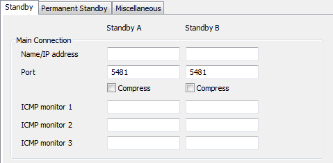
Use the Standby tab to configure the settings for the connection between the server on which you are working and the other Main and Hot Standby servers in the architecture.
The Standby tab’s settings are arranged in columns, with settings for Standby A and settings for Standby B (only available when the Type is set to Hot-Standby Pair or Triple Standby). Use the Standby A column settings to configure the connection between the server and one of the other Main/Hot Standby servers in the architecture. (A Hot Standby server is a server that may become either the Main server or remain a Standby server). On Triple Standby systems, the Standby B settings can be used to define the connection to the other Main/Hot Standby servers in the architecture.
The Standby tab contains the following sections:
- Main Connection—Use to configure the main connection between the server and the other server(s) in the system architecture. The Main Connection settings are:

- Name/IP Address—Use to define the name(s) or IP address(es) of the other server(s) in the system architecture (see Define the Names/IP Addresses of the Other Servers).
- Port—Use to define which ports are used by the other server(s) in the system architecture (see Define the Port Settings for a Server’s Connections).
- Compress—Use to enable or disable data compression for communications with each of the other servers in the system architecture (see Define the Server Compression Settings).
- ICMP Monitor 1—Use to define the IP address of the device that will be tested by an additional ICMP check (see Define the ICMP Monitor Settings for a Server).
- ICMP Monitor 2—Use to define the IP address of the device that will be tested by an additional ICMP check (see Define the ICMP Monitor Settings for a Server).
- ICMP Monitor 3—Use to define the IP address of the device that will be tested by an additional ICMP check (see Define the ICMP Monitor Settings for a Server).
- Backup Connection—Use to configure the backup connection between the server and the other server(s) in the system architecture. You only need to use the following Backup Connection settings if your system uses dual Ethernet connections:

- IP Address—Use to define the IP address(es) of the other server(s) in the system architecture (see Define the Names/IP Addresses of the Other Servers).
- Port—Use to define which ports are used by the other server(s) in the system architecture (see Define the Port Settings for a Server’s Connections).
- Compress—Use to enable or disable data compression for communications with each of the other servers in the system architecture (see Define the Server Compression Settings).
- ICMP Monitor 1—Use to define the IP address of the device that will be tested by an additional ICMP check (see Define the ICMP Monitor Settings for a Server).
- ICMP Monitor 2—Use to define the IP address of the device that will be tested by an additional ICMP check (see Define the ICMP Monitor Settings for a Server).
- ICMP Monitor 3—Use to define the IP address of the device that will be tested by an additional ICMP check (see Define the ICMP Monitor Settings for a Server).
- ICMP Monitors—Use to configure the ICMP polls that a ClearSCADA server sends to determine whether a remote computer is reachable. For more information, see Define the ICMP Poll Interval and Retry Count for a Server.

- Monitor—Use to define the timeout settings for the checks that are performed by the Main Connection and the Backup Connection. For more information, see Define the Monitor Timeout Settings for a Server.

Do not confuse the Heartbeat Timeout field on the Standby tab with the Heartbeat Timeout field on the Miscellaneous tab of the Partners settings.
- Transfer—Use to define the establishment and update settings for the Main-Standby communications:

- Interleave—A multiplier that is applied to the Transfer Interval (which is defined on the Miscellaneous tab). The Interleave allows you to define how often ClearSCADA will attempt to update the Standby server(s). For example, the Transfer Interval could be set to 5 seconds, with the Interleave set to 3 for the Standby A server. This means that ClearSCADA would attempt to update the Standby A server every 15 seconds (the Transfer Interval multiplied by the Interleave).
For more information, see Define the Transfer Interval and Transfer Timeouts.
- Connect Timeout—Define the amount of time, in seconds, that the server will wait for a connection to occur (see Define the Transfer Interval and Transfer Timeouts).
ATTENTION: Do not adjust the Connect Timeout setting of 60 unless instructed to do so by a Schneider Electric engineer. Incorrect use of the Connect Timeout setting can affect the establishment of new connections (may be unable to connect or only connect intermittently).
- Request Timeout—Define the amount of time, in seconds, that the server will wait for the Standby server to respond to a data transfer request (see Define the Transfer Interval and Transfer Timeouts). The default Request Timeout is 240.
- Duty Mode—Use to see Enable or Disable Duty Mode. Please be aware that Duty Mode is sometimes referred to as Duty Duty.
- Interleave—A multiplier that is applied to the Transfer Interval (which is defined on the Miscellaneous tab). The Interleave allows you to define how often ClearSCADA will attempt to update the Standby server(s). For example, the Transfer Interval could be set to 5 seconds, with the Interleave set to 3 for the Standby A server. This means that ClearSCADA would attempt to update the Standby A server every 15 seconds (the Transfer Interval multiplied by the Interleave).