Define the Required I/O Channel Configuration
Do not confuse I/O channels with Channel database items. The latter types of channel represent the telecommunications media via which Geo SCADA Expert communicates with a device such as an outstation or RTU.
The SCADAPack x70 tab on the configuration Forms of SCADAPack x70 I/O Modules includes a Channel Configuration section. You use the fields in the section to map the Analog, Digital, and/or Counter Configuration items to the relevant I/O channels on the I/O Module. The I/O channels represent the physical input and/or output capacity of the I/O module or SCADAPack x70 device.
For each input and output that is used on an I/O Module, or that is built into a SCADAPack x70 device, a SCADAPack x70 Configuration item of the appropriate type (Analog, Digital, or Counter) must exist in the Geo SCADA Expert database. In the Channel Configuration section of the SCADAPack x70 I/O Module database item, you use the Object Association fields to map each SCADAPack x70 Configuration item to the individual I/O channel that the Configuration item represents. To do this, you select the browse button that is next to the Object Association field that represents the relevant I/O channel. This displays a Reference browse window from which you select the required SCADAPack x70 Configuration item.
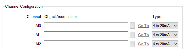
An engineer configures a SCADAPack x70 Analog Configuration item to represent an analog input on channel AI2 on a particular SCADAPack x70 I/O Module. They use the browse button next to the AI2 Object Association field to map the Configuration item to the relevant I/O channel on that module.
With analog input (AI) channels, a Type field is also available. Use the field to specify the operating mode and/or signal range of each analog input (see Specify the Required Analog Input and Output Settings).
With I/O Modules that include analog output (AO) channels, you typically use a single AO Output Type field elsewhere on the Form to specify the signal range for all of the analog outputs on the I/O Module (see Specify the Required Analog Input and Output Settings). However, some I/O Modules support Type fields that enable the signal range to be specified on a per analog input and output basis (see Specify the Required Analog Input and Output Settings).
The number and types of I/O channels that are available per I/O Module vary, depending on the SCADAPack x70 device's or module's I/O capacity (see Configure I/O Modules). For digital and analog inputs and outputs, the Channel labels (such as 'AI0') match those of the corresponding I/O channel on the physical device.
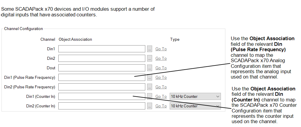
Some SCADAPack x70 devices and I/O modules support the ability for a number of digital input channels to have an associated counter or provide pulse rate frequency capabilities (see Configure I/O Modules).
With such I/O Modules, an additional Din (Pulse Rate Frequency) Channel entry is included in the Channel Configuration section for each digital input channel that provides pulse rate frequency capabilities (see Specify the Required Pulse Rate Frequency Settings). To use such a channel, you use the channel's Object Association field to specify the SCADAPack x70 Analog Configuration item that represents the analog input used on that channel.
The Channel Configuration section includes a Din (Counter In) Channel entry for each digital input channel that can have an associated counter (see Specify the Required Counter Input Type). To use the counter input on such a channel, you use the channel's Object Association field to specify the SCADAPack x70 Counter Configuration item that represents the counter input on that channel.