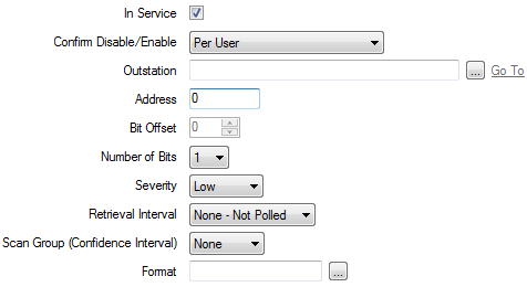
Use the fields at the top of the Digital Point tab to Configure Common Point Properties. Fields that are specific to digital points are explained below.

- Bit Offset—Only applies if the point resides within a Modbus Input Register or Holding Register address range (see SCADAPack Point Addressing). Use the spin box to specify the lowest (starting) bit of the point.
With a multi-bit point, ensure that all bits are consecutive (for example, a 2-bit digital might use bits 5 and 6, where bit 5 would be the starting bit). All the bits of a multi-bit point must reside consecutively in the same Word within a register range—bits for one point cannot continue into another Word. The range is 0 to 15.
It is important to be aware of the Word order in a Modbus device. For instance, the Word order is reversed when using ISaGRAF 32-bit variables. So, for example, if an ISaGRAF 32-bit variable is assigned network address 30001, as the Words are stored in reverse order in the Modbus device, this means that bits 0 to 15 are assigned the network address 30002, and bits 16 to 31 are assigned network address 30001.
The field is ‘grayed out’ and unavailable for use if the point is an Output Coil, or Input Discrete.
- Number of Bits—Use this combo box to specify the number of bits for the point. This corresponds to the number of consecutive 1-bit points that form the point.
The number of bits directly affects the number of point states (see Point State Properties). For further information, see Single and Multi-Bit Digital Points in the Geo SCADA Expert Guide to Core Point Configuration.
- Format—Specify the format in which the point’s value appears in other ViewX displays, such as Lists. For further information, see Define the Format of a Digital Point’s Values in the Geo SCADA Expert Guide to Core Point Configuration.