To Configure the Limits for a Counter-Type Point:
- Display the Form for the counter-type point that you want to configure.
- Select the <Point Type> tab (for example, select the Counter Point tab for a DNP3 counter point).
- Highlight the relevant Limit field. For example, if you are configuring the Hig limit, select the Limit field for the High row.

- Enter the required value. When you enter the value, you need to consider the requirements at the site—for example, the point limits need to correspond to normal/high/high-high operating conditions for the specific area of plant.
- Use the left-hand Severity combo box next to the Limit field to define what happens when the counter-type point’s value exceeds the limit:

- None—Geo SCADA Expert does not generate an alarm or event.
- Alarm—Geo SCADA Expert generates an alarm. The alarm has the severity level that you select in step 6.
- Fleeting—Geo SCADA Expert generates a fleeting alarm. The fleeting alarm has the severity level that you select in step 6. This option only is only available for the Normal state on points that support this feature.NOTICE
UNEXPECTED BEHAVIOR OF APPLICATION
Take care when configuring points to raise a fleeting alarm on transition back to the Normal state. Consider whether to configure such 'Return to Normal' alarms so that users are clearly able to distinguish between those alarms (which indicate a point's return to the normal operating state) and alarms that indicate an abnormal condition.Failure to follow these instructions can result in the unintended masking of the presence of other alarms. - Event—Geo SCADA Expert generates an event. The event has the severity level that you select in step 6.
If you selected the Alarm, Fleeting or Event options, proceed to step 6.
If you selected the None option, proceed to step 7.
- Use the right-hand Severity combo box next to the Limit field to define the level of importance associated with the event or alarm.
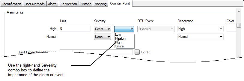
A set of severity levels are provided for each Geo SCADA Expert system (see Defining Severities in the Geo SCADA Expert Guide to Core Configuration). Choose the appropriate severity level from the list available on your system.
If any of the counter-type points on your system have Multiple Point State Alarms configured, an additional Alarm column is displayed to the left of the Description combo box. For information on specifying multiple Alarm Conditions, see Multiple Point State Alarms.
- Use the Description combo box to enter or select a suitable description of the limit.
You can either highlight the existing description and replace it with a new one, or you can choose one of the available descriptions from the combo box list. There are default descriptions for each limit, but these can be replaced by user-defined descriptions that are more specific to the points on your system (see Define Descriptions for Numeric Point States in the Geo SCADA Expert Guide to Server Administration).

Usually, the Description describes the state of the plant or conditions at the site. For example, for a counter point that monitors power consumption over a week, the description for a High-High limit could be ‘Excessive Demand’. The description provides extra information to operators so that they have a better understanding of what the High-High limit represents.
If the Dictionary feature is used on your system, you can prefix the string in Description field, in order for that string to be replaced with another term, when displayed in a List or on a Mimic, in ViewX. For more information, see Introduction to the Geo SCADA Expert Translation Dictionary in the Geo SCADA Expert Guide to the Translation Dictionary.
By default, point states are shown in black text on displays such as Lists, unless:
- The point is in an alarm state (in which case the text is displayed in the corresponding severity color)
- Another status, such as an Override, takes precedence over a non-alarm state (in which case the text is displayed in the color that indicates that status).
You can change the color that your system uses for the ‘Normal’ state (black by default), using the Color Palette (see Use the Color Palette to Define a Custom System Color in the Geo SCADA Expert Guide to Core Configuration).
If you want to associate a state with a custom color when neither of the above situations is in effect, proceed to step 8.
If you want the state to use the default color to indicate a ‘Normal’ state (black by default), proceed to step 10.
- Use the Color field to associate the limit with a custom color:
- Select the browse button next to the Color field for the limit you are configuring.
A Reference browse window is displayed.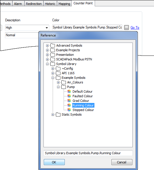
- Use the Reference browse window to locate the required custom color.
You can only associate a limit with a custom color if you have pre-configured custom colors available (see Defining a Custom State Color in the Geo SCADA Expert Guide to Core Configuration).
- Select the custom color.
- Select the OK button.
The Reference browse window is closed and the name of the selected color is shown in the Color field. When the point enters this state, its value will be shown in the custom color.
- Select the browse button next to the Color field for the limit you are configuring.
- Repeat steps 3-8 inclusive for each limit.
If theArea of Interest feature is enabled on your system, an Area of Interest field is displayed in the Alarm Limits section of the tab. Use the field to Specify the Area of Interest Associated with a Point’s State-Related Alarms and Events.
- Save the configuration.