Add and Configure the Entries in a Modbus Store Forward Table
You use the Modbus Store and Forward operation when there is no direct Modbus link between a host computer and the remote sites. To use this operation, you select the Enabled check box in the Modbus Store and Forward section on the Modbus tab of the SCADAPack x70 device (see Device Configuration Modbus Tab).
The situation of having no direct Modbus link can occur, for example, in radio networks where the host computer transmission is not in range of every remote site. It can also occur on systems where one controller is used as a data concentrator for several remote Modbus devices.
When you use this operation, a request that is sent to a Modbus device and cannot be directly accessed, is routed through an intermediate SCADAPack device. This intermediate device can communicate with both the host and the remote Modbus device.
The Modbus protocol provides Store and Forward operation through address translation. A SCADAPack configured for Store and Forward operation receives messages that are meant for a remote station, re-addresses them according to the translation table, and then forwards the message to the remote station. Responses from the remote station are processed in the same manner.
The Modbus protocol allows messages to be re-transmitted on the same port with address translation. With a radio system, the radio at the intermediate site is used as a type of repeater. The protocol allows messages to be re-transmitted on a different port, with or without address translation. This is used where the intermediate controller is a bridge between two networks.
The Modbus protocol driver maintains diagnostics counters at the Store and Forward site on the number of messages received and transmitted to aid in diagnosing unexpected communication events.
You use the Modbus Store Forward table to add a new route entry, edit, or delete an existing route entry. You can add a maximum of 128 Modbus Store and Forward route entries.
communication loss
In the Geo SCADA Expert database, the table is built into the SCADAPack x70 Device Configuration item to which it relates. Changes made to the routing configuration are downloaded to the SCADAPack x70 device when that device's Download Configuration pick action is next executed.
If you are to add, edit, or remove a Modbus/TCP Server, you have to enable the Modbus Store and Forward operation.
You can enable or disable the Modbus Store and Forward operation using either of the following options:
- Use the Enable Modbus Store and Forward check box on the Modbus Store Forward Table tab on the SCADAPack x70 Device Configuration item's tables.
- Use the Enabled check box in the Modbus Store and Forward section on the Modbus tab on the Form of the SCADAPack x70 Device Configuration item (see Enable or Disable the Modbus Tab).
By design, each of these options is in sync with the other. (If the configuration Form is open when the check box's setting is changed on the Table, you might have to close and then re-open the configuration Form in order for the check box on that Form to display its inherited value. Likewise, if the check box's setting is changed on the configuration Form while the Table remains open, you might have to close and then re-open the Table in order for the check box on that Table to display its inherited value.)
![]()
You specify these properties for each route in a SCADAPack x70 Modbus Store Forward Table:
The receiving server interface from which the message is received for each translation. Choose from:
- Serial 1—Only specify this option if it is configured for the Modbus device
- Serial 2—Only specify this option if it is configured for the Modbus device
- Serial 3—Only specify this option if it is configured for the Modbus device
- Serial 4—Only specify this option if it is configured for the Modbus device
- Serial 5 (Modem)—Only specify this option if it is configured for the Modbus device and only for SCADAPack 470 and SCADAPack 474.
- Modbus/TCP Server—This is the default. It applies to all Ethernet and PPP ports. You should enable the Modbus/TCP Server by enabling the Modbus IP Servers check box on the Settings tab of the SCADAPack x70 device (see Configure the Device Options).
The Modbus station address of the server message. This address should be different from the Modbus address assigned to the Incoming Interface.
- 0 to 255 (inclusive)—Specify the valid range when standard addressing is used for the serial interface and Modbus Broadcast is enabled.
- 1 to 255 (inclusive)—Specify the valid range when standard addressing is used for the serial interface and Modbus Broadcast is disabled.
- 0-65534 (inclusive)—Specify the valid range when extended addressing is used for the serial interface and Modbus Broadcast is enabled.
- 1-65534 (inclusive)—Specify the valid range when extended addressing is used for the serial interface and Modbus Broadcast is disabled.
- 1 to 255 (inclusive)—Specify the valid range when standard addressing is used for the Modbus/TCP interface.
- 1 to 65534 (inclusive)—Specify the valid range when extended addressing is used for the Modbus/TCP interface.
The default value is 1.
The interface from which the message is forwarded.
- Serial 1—Only specify this option if it is configured for the Modbus device
- Serial 2—Only specify this option if it is configured for the Modbus device
- Serial 3— This is the default. Only if it is configured for the Modbus device
- Serial 4—Only specify this option if it is configured for the Modbus device
- Serial 5 (Modem)—Only specify this option if it is configured for the Modbus device and only for SCADAPack 470 and SCADAPack 474
- Modbus/TCP Server—Requires a Forward IP Address to be assigned.
The Modbus station address of the forwarded message. This address should be different from the Modbus address assigned to the Forward Interface.
- 0 to 255 (inclusive)—Specify the valid range when standard addressing is used for the serial interface and Modbus Broadcast is enabled.
- 1 to 255 (inclusive)—Specify the valid range when standard addressing is used for the serial interface and Modbus Broadcast is disabled.
- 0-65534 (inclusive)—Specify the valid range when extended addressing is used for the serial interface and Modbus Broadcast is enabled.
- 1-65534 (inclusive)—Specify the valid range when extended addressing is used for the serial interface and Modbus Broadcast is disabled.
- 1 to 255 (inclusive)—Specify the valid range when standard addressing is used for the Modbus/TCP interface.
- 1 to 65534 (inclusive)—Specify the valid range when extended addressing is used for the Modbus/TCP interface.
The default value is 1.
The IP address of the Forward Station. This field is blank unless a TCP network is selected for the Forward Interface. Specify the Forward IP Address in the standard IPv4 address format. For example, 192.168.0.249.
The maximum time that the forwarding task waits for a valid response from the Forward Station.
The timeout should be less than or equal to the timeout set for the client message received on the Server Interface.
- 50 to 120000 (inclusive)—Specify the valid timeout range in milliseconds (ms). The default value is 2000.
- Display the Table for the relevant SCADAPack x70 Device Configuration item.
- Select the Modbus Store Forward Table tab to display the Modbus Store Forward Table.
- Select the Add Route button.
The Add Modbus Store Forward Route Entry dialog box is displayed.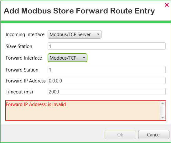
- Populate the fields as required (see above).
A diagnostic message indicates the fields that need populating with values that have to take a specific format, or for which at least one option needs selecting. The diagnostic message is removed once the fields are populated with values that have the required format
- Select the OK button to close the dialog box and add the entry to the table.
- Display the Table for the relevant SCADAPack x70 Device Configuration item.
- Select the Modbus Store Forward Table tab to display the Modbus Store Forward Table.
- Either:
- Double-click on the entry that you want to edit.
Or:
- Click on the route that you want to edit.
- Select the Edit Route button.
The Edit Modbus Store Forward Route Entry dialog box is displayed.
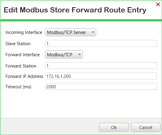
- Change the route's configuration as required.
- Select the OK button to confirm the changes, close the dialog box, and update the Modbus Store Forward Table.
- Display the Table for the relevant SCADAPack x70 Device Configuration item.
- Select the Modbus Store Forward Table tab to display the Modbus Store Forward Table.
- Select the entry for the route that is no longer required.
- Select the Remove Route button. (The button is only available for use when an entry is selected in the table.)
The route that was highlighted is removed from the table.
-
Click on the column heading by which you want to sort the entries in the table. (To reverse the sorting order, click on the same column heading again.) The order in which the entries are sorted does not impact on the routing functionality.
When you redisplay the table, the entries are listed in the order in which they were added to the table.